
Owner manual

4
Five-degree Indexing
(including 22.5° and 67.5° settings)
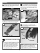
Loosen the actuator thumbscrew and pivot the
actuator tooth away from the notches located on the
perimeter of the protractor head. Loosen the large clamping
knob, Fig. 10.
Rotate the protractor head and fence to the desired
angle, then firmly engage the tooth on the actuator
with the corresponding notch on the protractor head.
The actuator tooth should point directly to the desired angle
on the scale. Tighten the large clamping knob, then tighten
the actuator thumbscrew, Fig. 11.
Operation – Changing Angle Settings
1
2
FIG. 10
FIG. 11
Pivot actuator
tooth away from
protractor head
Large
clamping
knob
Actuator
thumbscrew
Tighten large
clamping knob
then tighten
actuator
thumbscrew
Actuator tooth,
firmly engaged with
notch on
protractor head
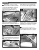
Continuous Adjustments (for angle settings
finer than 5° increments)
Pivot the actuator tooth away from the notches on the
protractor head, aligning the arm over the miter slot, and
tighten the thumbscrew. Now loosen the small nylon
thumbscrew on the actuator and pivot the
1
⁄2 ° cursor toward
the scale. Rotate the cursor until it is aligned edge to edge
with the scale and tighten the thumbscrew. When you change
miter angles, just align the desired angle on the scale with the
“0” cursor line. For
1
⁄2 ° adjustments align the mark on the
scale with the “.5” cursor line. Fig 12.
FIG. 12
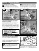
FIG. 13
Adding a wooden subfence to the front of the MITER1000
fence is easy to do and offers several benefits. You can
extend the length or height of the standard fence, and by
extending the subfence to cross the line of cut, it provides
zero clearance backing for tearout control. Use the drill and
counterbore dimensions shown in Fig. 13. Adjust the height
and length to match your applications. Fasteners are
provided in your hardware pack.
Attaching Auxiliary Fences
Made in America by: Taylor Design Group, Inc.
P.O. Box 810262, Dallas, Texas 75381, 972-418-4811, www.incra.com
Printed in the U.S.A. © 2000, Taylor Design Group, Inc.
INCRA is a registered trademark of Taylor Design Group, Inc.
08-2000
Pivot actuator tooth away from
protractor and tighten thumbscrew
#10-32
hex nut
3
⁄4"
1
⁄4" thru hole with
5
⁄8" dia. x
5
⁄16" deep
counterbore
#10flat
washer
#10-32
machine
screw
Cut to
desired
height
9
⁄16"
Arm aligned
with miter
slot
Pivot cursor to scale
To increase holding power when crosscutting or
mitering, add a strip of adhesive backed sand
paper to the front face of your wooden auxiliary fence.
Use 150 to 180 grit sandpaper.
Caution:
After making any
adjustments to the miter angle of your
INCRA Miter1000, always verify saf
e
clearance between the fence and the blade
bef
ore turning on the saw.