
Pre-Delivery/Install Checklist


2_Eng 200-2954_Rev. D_4/4/17
CHANGING THE AIR FILTER(S)
Dirty air lter(s) will reduce the compressor’s performance and life. To avoid any
internal contamination of the pump, the lters should be replaced on a regular
basis. Do not allow the lters to become lled with excessive dirt or paint.
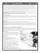
Filter replacement
1. Remove the wing nut and remove the outer cover. Check the condition of the
lter. If the lter element it is dirty or lled with paint, replace it.
2. Place the outer cover back over the lter element and secure with the wing
nut.
ADJUSTING BELT TENSION / REPLACING BELTS
NOTE: Proper belt tension and pulley alignment must be maintained for maximum drive efciency and belt life. If belts
are too tight, additional load will be placed on the motor and motor bearings.
WARNING: Risk of unsafe operation. This unit cycles automatically when the power is on. When performing mainte-
nance, you may be exposed to voltage sources, compressed air, hot surfaces or moving parts. Personal injuries can
occur. Before performing any maintenance or repair, always disconnect (“Lock Out” / “Tag Out”) the main power source
from the compressor, bleed off all air pressure and allow the unit to cool. Do not operate the unit with the shrouds or
guards removed.
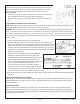
1. Remove belt guard and loosen the motor mounting bolts.
2. Replace or adjust the belts to be centered in the grooves on the ywheel and
motor pulley. Shift the motor back to the point where the correct deection exists.
Tighten two outside motor mounting bolts enough to hold the motor in place for
checking pulley and ywheel alignment. The belt should deect 1/2” (13 mm)at
midway between the pulley and the ywheel when a 10 pound (4.6 kg.) weight is
applied at the midway point.
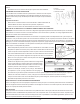
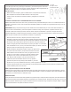
3 Check for proper pulley alignment. Place a straightedge
against the outside of the ywheel and the motor drive
pulley. Measure the distance between the edge of the belt
and the straightedge at points A1 and A2 in gure. The
difference between measurements should be no more than
1/16” (1.6mm). If the difference is greater than 1/16”
(1.6mm) loosen the set screw or hub bolts holding the
motor drive pulley to the shaft. Adjust the pulley’s position
on the shaft until the A1 and A2 measurements are within
1/16” (1.6 mm) of each other and retighten too the motor shaft.
4. When proper belt tension is achieved and the pulley is aligned, tighten all four motor mounting screws. Reinstall the
belt guard.
CHECK THE PRESSURE RELIEF VALVE(S)
Pull the ring(s) on the pressure relief valve(s) daily to ensure that it is operating properly and to clear the valve of any
possible obstructions. If the valve is stuck or does not operate smoothly, it must be replaced with the same pressure
and CFM rated valve.
TESTING FOR LEAKS
Check that all connections are tight. A small leak in any of the hoses, transfer tubes, or pipe connections will sub-
stantially reduce the performance of your air compressor. If you suspect a leak, spray a small amount of soapy water
around the area of the suspected leak with a spray bottle. If bubbles appear, repair or replace the faulty component. Do
not over tighten any connections.
F = Wing nut(s)
G = Cover(s)
H = Filter element(s)
Downward Force
Deflection