200-2831 Operator-Parts Manual Revision B Manuel de l’opérateur - Manuel de pièces Manual del operador - Manual de piezas Single Stage, Belt Drive, Gasoline Engine Driven Air Compressor D’une seule étape, actionnement pour courroie, compresseur d’air motorisés d’essence De una sola etapa, accionamiento por correa, compresore de aire conducidos motor de la gasolina Product style and configuration may vary. Le style et la configuration du produit peuvent varier.
TABLE OF CONTENTS SAFETY GUIDELINES . . . . . . . . . . . . . . . . . . . . . . . . . . . . . . 3 PARTS DRAWINGS AND PARTS LISTS . . . . . . . . . . . . 29-34 OVERVIEW . . . . . . . . . . . . . . . . . . . . . . . . . . . . . . . . . . . . . . . 6 ASSEMBLY . . . . . . . . . . . . . . . . . . . . . . . . . . . . . . . . . . . . . . . 7 COMPRESSOR CONTROLS . . . . . . . . . . . . . . . . . . . . . . 8-11 OPERATING INSTRUCTIONS . . . . . . . . . . . . . . . . . . . . 12-17 MAINTENANCE . . . . . . . . . . . .
SAFETY GUIDELINES The following information relates to protecting YOUR SAFETY and PREVENTING EQUIPMENT PROBLEMS. To help you recognize this information, we use the following symbols. Please read the manual and pay attention to these sections. DANGER: – A POTENTIAL HAZARD THAT WILL CAUSE SERIOUS INJURY OR LOSS OF LIFE. WARNING: – A POTENTIAL HAZARD THAT COULD CAUSE SERIOUS INJURY OR LOSS OF LIFE. CAUTION: – A POTENTIAL HAZARD THAT MAY CAUSE MODERATE INJURY OR DAMAGE TO EQUIPMENT. 9. WARNING 1. 2.
CONSIGNES DE SÉCURITÉ Les informations suivantes concernent VOTRE SÉCURITÉ et LA PROTECTION DU MATÉRIEL CONTRE LES PANNES. Pour vous aider à identifier la nature de ces informations, nous utilisons les symboles suivants. Veuillez lire le manuel et prêter attention à ces sections. DANGER: – DANGER POTENTIEL POUVANT ENTRAÎNER DE GRAVES BLESSURES OU LA MORT. AVERTISSEMENT: – DANGER POUVANT CAUSER DES BLESSURES GRAVES VOIRE MORTELLES.
PAUTAS DE SEGURIDAD La información que sigue se refiere a la protección de SU SEGURIDAD y la PREVENCIÓN DE PROBLEMAS DEL EQUIPO. Como ayuda para reconocer esta información, usamos los siguientes símbolos. Lea por favor el manual y preste atención a estas secciones. PELIGRO: - UN POSIBLE RIESGO QUE CAUSARÁ LESIONES GRAVES O LA PÉRDIDA DE LA VIDA. ADVERTENCIA: - UN RIESGO POTENCIAL QUE PODRÍA PROVOCAR GRAVES LESIONES O MUERTE.
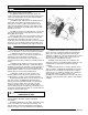
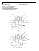
OVERVIEW \ VUE D’ENSEMBLE \ RESUMEN GENERAL BASIC AIR COMPRESSOR COMPONENTS Fig. 1 The basic components of the air compressor are the gasoline engine, pump, tank and unloader. The gasoline engine (see A) powers the pump. The engine drives a pulley and belt, which transfers power from the engine to the pump pistons via a flywheel and a crankshaft. The flywheel fan helps cool the pump. The pump (see B) compresses the air and discharges it into the tank.
INSTALLATION / INSTALLATION / INSTALACION 1. 2. 3. INSTALLING THE COMPRESSOR Unpack the air compressor. Inspect the unit for damage. If the unit has been damaged in transit, contact Customer Service. Do this immediately, because there are time limitations to damage claims. The unit should include: • The air compressor • The operator and parts manual • The engine manual • Air hose (CWA5591016.
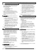
COMPRESSOR CONTROLS / COMMANDES DU COMPRESSEUR / CONTROLES DEL COMPRESOR COMPRESSOR CONTROLS Pressure Relief Valve (see A) This valve will pop open automatically to prevent overpressurization if the unloader does not switch the engine to idle when the tank pressure reaches the pre-set level. To operate manually, pull the ring on the valve to relieve air pressure in the tank. Tank Pressure Gauge (see B) This gauge measures the pressure level of the air stored in the tank.
COMPRESSOR CONTROLS / COMMANDES DU COMPRESSEUR / CONTROLES DEL COMPRESOR Conector rápido, 1/2" (vea H) Mecanismo de liberación rápida para conectar y desconectar la unidad H4X. Se conecta fácilmente a una manguera de aire de 1/2" para suministrar aire sin restricciones del compresor a la unidad H4X. Orificios no regulados (vea J) Para conectar otro conector rápido o manguera de aire de 1/2". Conector rápido, 1/2" (vea I) (únicamente CWA5591016.
H4X REMOTE AIR HUB / CENTRE DE DISTRIBUTION À DISTANCE H4X / MÓDULO REMOTO DE AIRE H4X USING THE H4X REMOTE HUB 1. 2. Rotate the handle (B) up to unlock. Push down on the quick coupler (B) and slide the H4X hub up to release it from the docking station. 3. Connect one end of a 1/2” air hose (C) to the quick coupler (D) and the other end to the connector on the H4X remote hub (E). 4. Use the supplied holes (F) to securely mount the H4X remote hub to any surface. 5.
H4X REMOTE AIR HUB / CENTRE DE DISTRIBUTION À DISTANCE H4X / MÓDULO REMOTO DE AIRE H4X Fig. 3 Fig.
BREAK-IN OF THE PUMP \ RODAGE DE LA POMPE \ MARCHA DE LA BOMBA BREAK-IN OF THE PUMP NOTE: When references are made to gasoline engine operations, refer to the engine manual for proper procedure. 1. Before starting the compressor for the first time, ensure proper oil level in the gasoline engine crankcase. 2. 3. 4. 5. WARNING: Risk of carbon monoxide poisoning. Engine exhaust contains carbon monoxide, an odorless and deadly poison. DO NOT operate in an enclosed area.
RODAGE DE LA POMPE \ MARCHA DE LA BOMBA MARCHA INICIAL DE LA BOMBA 1. Antes de arrancar el compresor por primera vez, añada aceite al cárter del motor de gasolina. Consulte el manual del motor sobre los requerimientos de aceite. Fig. 7 Run position Position de passage Posición de funcionamiento C Start position Position de début Posición de comienzo D ADVERTENCIA: Riesgo de envenena-miento por monóxido de carbono. El escape del motor contiene monóxido de carbono, un veneno inodoro y mortal.
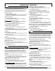
OPERATING INSTRUCTIONS \ MODE D’EMPLOI 1. 2. 3. 4. 5. DAILY STARTUP Check the oil level in the gasoline engine crankcase. Add oil as necessary. See instructions in the engine manual. Check the oil level in the pump (see “Checking the Oil” in the maintenance section). Fill the tank of the gasoline engine with unleaded gasoline. Move the unloader lever to the start (vertical) position (see D). Close the tank petcock (see F).
MODE D’EMPLOI \ INSTRUCCIONES OPERATIVAS ARRANQUE DIARIO 1. 2. 3. 4. 5. Revise el nivel del aceite en el cárter del motor de gasolina. Añada aceite según sea necesario. Consulte las instrucciones en el manual del motor. Compruebe el nivel de aceite de la bomba (ver "Verificación del nivel de aceite" en la sección de Mantenimiento). Llene el tanque del motor con gasolina sin plomo. Mueva la palanca de la válvula del descargador a la posición empiezan (vertical) (vea D).
OPERATING INSTRUCTIONS \ MODE D’EMPLOI \ INSTRUCCIONES OPERATIVAS COLD WEATHER STARTING (Temperatures less than 32°F) For the gasoline engine, cold weather preparation includes a clean air filter, a good spark plug gapped to engine manufacturer’s specifications and proper oil as recommended in the engine manual. 4. WARNING: The pump head and transfer tube become very hot when running.
OPERATING INSTRUCTIONS \ MODE D’EMPLOI \ INSTRUCCIONES OPERATIVAS 1. 2. SHUTDOWN Shut off the gasoline engine. Reduce pressure in the tank through the outlet hose. You can also pull the relief valve ring (see G) and keep it open to relieve pressure in the tank. Fig. 14 G CAUTION: Escaping air and moisture can propel debris that may cause eye injury. Wear safety goggles when opening petcock. 3.
MAINTENANCE \ ENTRETIEN \ MANTENIMIENTO MAINTENANCE WARNING: To avoid personal injury, always shut off the gasoline engine and relieve all air pressure from the system before performing any service on the air compressor. Regular maintenance will ensure trouble–free operation. Your gas powered air compressor represents high–quality engineering and construction; however, even high–quality machinery requires periodic maintenance. The items listed below should be inspected on a regular basis.
MAINTENANCE \ ENTRETIEN \ MANTENIMIENTO DRIVE BELT TENSION ADJUSTMENT MANTENIMIENTO ADVERTENCIA: Para evitar lesiones personales, WARNING: To avoid personal injury, always shut off siempre apague y desenchufe el compresor y alivie toda la presión de aire del sistema antes de realizar algún tipo de servicio en el compresor de aire. the gasoline engine and relieve all air pressure from the system before performing any service on the air compressor.
MAINTENANCE \ ENTRETIEN \ MANTENIMIENTO (Fig. 18) Fig. 17 1. En utilisant une clé de taille appropriée, dévisser les écrous de compression (E) sur le clapet de non-retour (F) et la tête de la pompe (G). Retirer le tuyau de transfert. 2. Enlever l’avant de l’écran de protection de la courroie en tournant les 4 agrafes (H) de retenue de la courroie d’un quart de tour en utilisant une clé de 5/8 po. 3. Desserrez les boulons de montage du moteur (I). 4. Desserrer le boulon de la barre stabilisatrice (J). 5.
MAINTENANCE \ ENTRETIEN \ MANTENIMIENTO (Fig. 18) ALINEACIÓN DE LA POLEA 1. Using the appropriately sized wrench, loosen the compression nuts (E) on the check valve (F) and pump head (G). Remove the transfer tube. 2. Remove the front of the beltguard by turning the 4 belt guard clips (H) 1/4 turn counter-clockwise using a 5/8” wrench. 3. Loosen the engine mounting bolts (I). 4. Loosen the stabilizer bar bolt (J). 5. Loosen the setscrew on the engine pulley. 6.
MAINTENANCE \ ENTRETIEN \ MANTENIMIENTO siempre apague y desenchufe el compresor y alivie toda la presión de aire del sistema antes de realizar algún tipo de servicio en el compresor de aire. DRIVE BELT REPLACEMENT WARNING: To avoid personal injury, always shut off the gasoline engine and relieve all air pressure from the system before performing any service on the air compressor. (Fig. 18) 1. Using the appropriately sized wrench, loosen the compression nuts (E) on the check valve (F) and pump head (G).
MAINTENANCE \ ENTRETIEN \ MANTENIMIENTO 9. Replace the transfer tube and tighten compression nuts. 10. Perform the “Break-in of the pump” procedure in the Operating Instructions to make sure there are no leaks and the check valve is working properly. POUR REMPLACER OU NETTOYER LE CLAPET DE NON-RETOUR AVERTISSEMENT: Pour éviter les risques de blessures, arrêtez toujours le moteur à essence et libérez toute la pression d’air dans le circuit avant d’effectuer l’entretien du compresseur d’air. (Fig.
MAINTENANCE \ ENTRETIEN \ MANTENIMIENTO CLEANING THE AIR FILTER A dirty air filter will reduce the compressor’s performance and life. To avoid any internal contamination of the pump, the filter should be cleaned frequently, and replaced on a regular basis. Felt filters should be cleaned in warm, soapy water, rinsed, and allowed to air dry before reinstallation. Paper filters should be replaced when dirty. Do not allow the filter to become filled with dirt or paint.
SERVICE INTERVAL Perform the following maintenance at the intervals indicated below. Inspect and clean air filter . . . . . . . . . . . . . . . . . . . . . . . . . . . . . . . . . . . . . . . . . . . . . . .Daily Check pump oil level . . . . . . . . . . . . . . . . . . . . . . . . . . . . . . . . . . . . . . . . . . . . . . . . . . .Daily Check engine oil level . . . . . . . . . . . . . . . . . . . . . . . . . . . . . . . . . . . . . . . . . . . . . . . . . .Daily Change pump oil . . . . . . . . . . . . . .
TROUBLESHOOTING CHART Note: Troubleshooting problems may have similar causes and solutions. PROBLEM POSSIBLE CAUSE SOLUTION Low Discharge Pressure Air leaks Leaking valves Tighten or replace leaking fittings or connections. Do not overtighten. Contact authorized service center. Restricted air intake Clean or replace air filter element(s). Blown gaskets Contact authorized service center. Worn piston rings or cylinder Contact authorized service center.
DÉPANNAGE Remarque : Les problémes de dépannage peuvent avoir des causes et des solutions similaires. PROBLÈME CAUSE POSSIBLE SOLUTION Pression de décharge insuffisante Fuites d’air Serrez ou remplacez les raccords ou les connexions qui ne sont pas étanches. Ne serrez pas trop. Contactez le centre d’entretien agréé.
CUADRO DE DETECCIÓN DE FALLOS Nota: Los problemas de deteccion de fallos pueden tener causas y soluciones similares. PROBLEMA CAUSA POSIBLE Baja presión de descarga Fugas de aire Golpeteo de la bomba del compresor Aceite en el aire de descarga Sobrecalentamiento Ajuste o reemplace los accesorios o las conexiones con fugas. No ajuste demasiado. Válvulas con fugas Póngase en contacto con el centro de servicio autorizado. Entrada de aire restringida Limpie o reemplace los elementos del filtro de aire.
PARTS DRAWING / DESSIN DES PIÈCES / ESQUEMA DE LA PIEZAS 7a 7b PARTS LIST / LISTE DE PIÈCES / LISTA DE LAS PIEZAS Item Art Art 1 2 3 4 5 6 7 7a 7b 8 9 10 11 12 13 14 15 or Part No.
Note: Tighten compression nut handtight plus 1 full turn. Note: Serrez l'écrou de compactage solide plus 1 plein tour. Nota: Apriete la tuerca de la compresión handtight más 1vuelta completa.
PARTS LIST / LISTE DE PIÈCES / LISTA DE LAS PIEZAS Item Art Art 1 2 3 4 5 6 7 8 9 10 11 12 13 Part No.
PARTS LIST / LISTE DE PIÈCES / LISTA DE LAS PIEZAS Item Art Art 52 Part No. No / P Núm / P 090-0027 53 54 55 56 57 58 59 N/A N/A 098-2278 098-1021 098-2856 072-0002 059-0396 Qty Qté Cant Description 1 Throttle control valve Elbow, street 1/4 X 90° Nipple, close 1/4-18 NPT Label, warning, not shown Label, warning, not shown Label, warning Petcock, 1/8" Bolt, 5/16-18 X 3.5", fully threaded (model CWA5591016.4 only) 60 114-0751 1 Bracket, belt tensioner (model CWA5591016.
PARTS DRAWING / DESSIN DES PIÈCES / ESQUEMA DE LA PIEZAS 165 Pump Assy Sequence #’s 1, 2, 3, 4, 5, 6, 7 & 8 Torque to 220–300 lbs-in Pump Specifications Weight–39 lbs. Oil Capacity (approx.)–18 oz. Min. RPM–700 Max, RPM–1200 Max.
PARTS LIST / LISTE DE PIÈCES / LISTA DE LAS PIEZAS 165 Pump Assy Item Artículo Article 1 2 3 4 5 6 Part No. Núm / P No / P 059-0144 054-0112 048-0065 047-0092 051-0043 046-0149 Qty Cant Qté 8 1 2 2 1 1 7 045-0053 1 Carrier, includes items 5 & 12 8 9 10 11 12 13 14 15 16 17 18 19 20 N/A N/A 060-0053 044-0064 046-0161 053-0043 051-0013 049-0050 046-0263 077-0148 061-0113 061-0112 056-0019 4 1 1 1 1 1 1 1 1 1 14 1 1 Screw, 5/16-18 x 1” lg Screw, 5/16-18 x 1.
PARTS AND SERVICE Replacement parts and service are available from your nearest authorized Service Center. If the need arises, contact Product Service as listed at right. When needing service, please contact the nearest authorized Service Center or call: When consulting with a Service Center or Product Service, refer to the model number and serial number located on the serial label of the compressor. Proof of purchase is required for all transactions and a copy of your sales receipt may be requested.
Made in USA with domestic and foreign components Fabriqué aux États – Unis à l’aide de composants de l’intérieur et de l’étranger Hecho en EE.UU.con componentes domésticos y extranjeros ©2010 Sanborn Mfg. Division of MAT Industries, LLC. Springfield, MN 56087 1-888-895-4549 All Rights Reserved. Tous droits réservés. Reservados todos los derechos.