
Use and Care Manual

10 - ENG
200-2903
MAINTENANCE
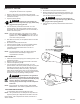
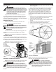
NOTE: Once the motor pulley has been moved from its factory
set location, the grooves of the flywheel and pulley must
be aligned to within 1/16” to prevent excessive belt wear.
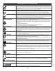
To check pulley alignment, remove the belt guard and place
a straightedge (see A) against the pump flywheel (see B) (See
Fig. 9). Measure and record the distance from the straightedge to
the edge of the drive belt at point C. Then measure the distance
from the straightedge to the edge of the drive belt again at points
D and E. Both distances should be the same as at point C. If D
or E are different from C, there is a misalignment which must
be corrected before the compressor is run. To correct a pulley
misalignment, use the following procedure.
1. Remove the front of the beltguard by turning the 4 belt guard
clips 1/4 turn using a 5/8” wrench.
2. Loosen the motor mounting bolts.
3. Loosen the setscrew on the motor pulley.
4. Align the motor pulley with the pump flywheel (C-D-Emust
beequal).
5. Retighten the motor pulley setscrew to 85-90 in.-lbs.
6. Adjust the proper belt tension.
7. Retighten the motor mounting bolts to 130-180 in.-lbs.
8. Reinstall the belt guard. All moving parts must be
guarded.
Thisunitstartsautomatically.
ALWAYSshutoffthemainpowerdisconnect,and
bleedallpressurefromthesystembeforeservicing
thecompressor,andwhenthecompressorisnotin
use.Donotusetheunitwiththeshroudsorbelt
guardremoved.Seriousinjurycouldoccurfrom
contactwithmovingparts.
1. Remove the front of the beltguard by turning the 4 belt guard
clips 1/4 turn using a 5/8” wrench.
2. Loosen the motor mounting bolts.
3. Shift the motor towards the pump to the point where the belt
can be easily removed and installed.
4. Remove and replace belt. NOTE: The belt must be centered
over the grooves on the flywheel and motor pulley.
5. Shift the motor back to the point where the correct deflection
exists (see “Drive Belt Tension Adjustment”).
6. Retighten the motor mounting bolts to 130-180 in.-lbs.
7. Check to ensure that the tension remained correct.
8. Reinstall the belt guard. All moving parts must be guarded.
Thisunitstartsautomatically.
ALWAYSshutoffthemainpowerdisconnect,and
bleedallpressurefromthesystembeforeservicing
thecompressor,andwhenthecompressorisnotin
use.Donotusetheunitwiththeshroudsorbelt
guardremoved.Seriousinjurycouldoccurfrom
contactwithmovingparts.
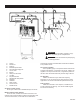
1. Turn air compressor off,
remove the power cord from
the outlet or lock out the
power supply and relieve all
the air pressure from the tank
(refer to “Shutdown” in
Operating Instructions).
Make sure the compressor
has cooled down before
servicing.
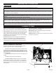
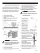
2. Using the appropriately
sized wrench, loosen the
compression nuts (A) on
the check valve (B) and
pump head (C). Remove
the transfer tube (D).
3. Using the appropriately
sized wrench, loosen the
compression nut (F) from the
connector (G), located on the side of the check valve.
Remove the bleeder tube (E) and gently push aside.
4. Making note of the orientation for reassembly, unscrew the
check valve from the tank (counterclockwise) using a 1-3/16”
open end wrench.
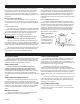
5. Using a pencil or screwdriver, carefully
push the valve disc up and down. If the
valve disc does not move freely up and
down, the check valve needs to be
cleaned or replaced.
6. Clean the check valve with warm soapy
water and make sure to dry thoroughly
before reinstalling. If the disc valve still
does not move freely up and down, it will
need to be replaced.
7. Apply thread sealant to the check valve
threads and reinstall into the tank by
turning clockwise. Make sure it is the
same orientation as when it was
removed.
8. Replace the bleeder tube and tighten compression nut.
9. Replace the transfer tube and tighten compression nuts.
10. Perform the “Break-in of the pump” procedure in the
Operating Instructions to make sure there are no leaks and
the check valve is working properly.
Fig. 9
TO REPLACE OR CLEAN CHECK VALVE
WARNING:
DRIVE BELT REPLACEMENT
WARNING: