
Use and Care Manual

5 - ENG
200-2903
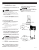
This compressor was shipped with oil in the pump
crankcase.Checkoilbeforeoperatingtheair
compressor,seeCheckOilunderMaintenance.
1. Unpack the air compressor. Inspect the unit for damage. If
the unit has been damaged in transit, contact the carrier
and complete a damage claim. Do this immediately
because there are time limitations to damage claims.
The carton should contain:
• aircompressor
• operator/partsmanual
2. Check the compressor’s serial label to ensure that you
have received the model ordered, and that it has the
required pressure rating for its intended use.
3. Locate the compressor according to the following
guidelines:
a. For optimum performance, locate the compressor close
to the power panel, as specified in ELECTRICAL
POWER REQUIREMENTS, and as close as possible to
the place where the air will be used. This ensures
maximum power to the compressor and maximum air
pressure to the tool. If both of these conditions
cannot be met, it is better to locate the compressor
close to the power panel, and use a longer air hose
to reach the usage area.
b. The flywheel side of the compressor must be at least
12 inches (31 cm) from any wall or obstruction, in a
clean, well-ventilated area, to ensure sufficient air
flow and cooling.
c. In cold climates, locate the compressors in a
heated building when not in use. This will reduce
problems with lubrication, motor starting and freezing
of water condensation.
d. Remove the compressor from the shipping pallet and
place it on the floor or a hard, level surface. The
compressor must be level to ensure proper
lubrication of the pump and good drainage of the
moisture in the tank.
CAUTION:
The shipping pallet is not designed as a
baseforanoperatingcompressor.Operatingthe
compressor while it is on the pallet will void your
warranty.
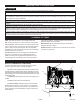
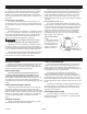
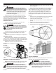
e. To prevent damage to tank and pump, the tank must be
shimmed so the pump is level within 1/8” per lineal foot
maximum to distribute oil properly. Fasten to floor and
NEVER force tank feet to floor without shims when
tightening. We also recommend the use of vibration
pads (094-0137) under tank feet (E).
4. Connect an air hose (not included) to the compressor.
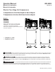
ASSEMBLY
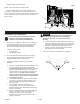
ASSEMBLING THE COMPRESSOR
Fig. 2
F
Magnetic starter (required) (see E).
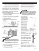
NOTE: These units require a magnetic starter.
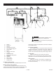
Magnetic starters that are not factory- mounted on the
compressor can be mounted on the wall if desired. Mount as
close to compressor as possible. Size the wires, protect them with
conduit, and provide branch circuit protection per the National
Electrical Code.
Fig. 1a
E