
Use and Care Manual

7 - ENG
200-2903
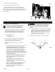
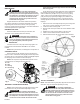
Main Power Disconnect
Install a main power disconnect switch in the power line to
the compressor, near the compressor’s location. It is operated
manually, but when it is in the ON position, the compressor
will start up or shut down automatically based on air demand.
ALWAYS operate this switch to OFF when the compressor is not
being used.
Magnetic Starter Reset Switch
If the motor shuts down because of overload, wait 10–15
minutes so the motor can cool down, then press (NEVER force)
the reset switch on the front of the magnetic starter to restart the
motor.
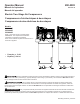
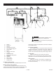
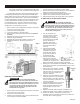
Pressure switch (see A)
This switch turns on the compressor. It is operated manually,
but when in the ON position, it allows the compressor to start up
or shut down automatically, without warning, upon air demand.
ALWAYS set this switch to OFF when the compressor is not
being used, and before unplugging the compressor.
Foryoursafety,tankpressureispreset
withintheswitchandmustneverbetamperedwith.
This switch must not be adjusted by the operator; doing so
will void the warranty. The pressure switch controls the level of
air pressure in the tank by automatically starting and stopping the
motor, as required to maintain the factory preset pressure level.
The pressure switch also automatically bleeds pressure from
the pump head when the pump stops. This feature eliminates
back pressure in the pump, ensuring easier starting.
TankSafetyValve (see B)
Used to allow tank pressure to escape into the atmosphere.
If the pressure switch does not shut off the compressor at it’s “cut-
out” pressure setting, the safety valve will protect against high
pressure by releasing tank pressure at it’s factory set pressure
(slightly higher than the pressure switch “cut-out” setting). To
operate manually, pull the ring on the valve to relieve air pressure
in the tank.
Pressure Release Valve (see C)
The pressure release valve (located on the bottom of the
pressure switch), is designed to release compressed air from the
compressor head and outlet tube when the compressor reaches
“cut-out” or is shut off. The pressure valve allows the motor to
restart freely. When the motor stops running, air will be heard
escaping from this valve for a few seconds. No air should be
heard leaking when the motor is running or after brief release
after reaching “cut-out” pressure.
TankPressureGauge
(see D)
This gauge measures
the pressure level of the
air stored in the tank. It
is not adjustable by the
operator, and does not
indicate line pressure.
Fig. 3
COMPRESSOR CONTROLS
Refer to the air compressor’s serial label for the unit’s voltage
and amperage requirements. Ensure that all wiring is done by
a licensed electrician, in accordance with the National Electrical
Code. Use electrical conduit to protect the wiring.
Forbestperformanceandreliablestarting,theair
compressormustbeinstalledonadedicatedcircuit,as
closeaspossibletotheelectricalpowerpanel. Provide
circuit breaker or fuse protection at your main power panel. Use
time delay fuses on the circuit, because the compressor will
momentarily draw several times its specified amperage when first
started.
Install a main power disconnect switch in the line from the
panel to the compressor. The main power disconnect switch
must be located near the compressor, for ease of use and safety.
When turned OFF, the main power disconnect switch shuts off all
power to the compressor. When it is turned ON, the compressor
will start and stop automatically, controlled by the pressure
switch.
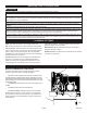
These air compressors require a magnetic starter, to prevent
motor damage in the event of a thermal overload.
Low voltage will cause difficult starting or an overload. Low
voltage can be caused by a low supply voltage from the local
power company, other equipment running on the same line, or
inadequate wiring. If any other electrical devices are drawing from
the compressor’s circuit, it may fail to start.
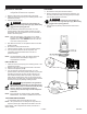
Low voltage to the compressor can be caused by a
supply wire of insufficient gauge for the distance between the
compressor and the power source. The longer the distance, the
larger the wire gauge (lower the number) must be, to overcome
the inherent voltage loss caused by the wire resistance. Refer to
the National Electrical Code to determine proper wire size for your
circuit.
If the wiring is not adequate, the input voltage will drop by 20
to 40 volts at startup. Low voltage or an overloaded circuit can
result in sluggish starting that causes the circuit breaker to trip,
especially in cold conditions.
This product must be connected to a grounded, metallic,
permanent wiring system, or an equipment - grounding terminal
or lead on the product.
A
D
B
(Measures pressure in
tank, not line pressure)
WARNING:
ELECTRICAL POWER REQUIREMENTS
ELECTRICAL WIRING
MAIN POWER PANEL
MAIN POWER DISCONNECT SWITCH
LOW VOLTAGE PROBLEMS
GROUNDING INSTRUCTIONS
C
MAGNETIC STARTER