
User Manual


CHC-15 CRYSTAL HOLDER & GC-15 GLASS CELL
2 CRYSTAL HOLDER DESCRIPTION
The CHC-15 Crystal Holder is designed to mate with a ChemGlass O-ring Joint P/N CG-124-04 or
equivalent. This allows the user to create his own experimental cell around the O-ring Joint.
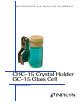
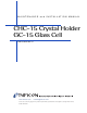
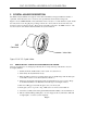
Figure 1 shows a INFICON CHC-15 Crystal Holder. It has a cavity for a 1-inch diameter crystal. Inside
the cavity there are two Pogo® pins providing connections to the crystal’s front and rear electrodes.
Note the locations of the Pogo® pins. These pins are internally connected to the SMB connector. Also
note the location of the index hole that identifies the crystal orientation.
Figure 1 CHC-15 Crystal Holder
2.1.1 HOW TO INSTALL A CRYSTAL IN A INFICON CRYSTAL HOLDER
Since the crystals have to be changed periodically, this is an important step with which to become
thoroughly familiar:
1. Identify the Front and Rear Sides of the crystal. See Section 2.2.1.
2. Clean & Dry the Crystal Holder cavity.
3. Place the CHC-15 between your index finger and your middle finger with the Index pin
of the CHC-15 at the 3 O’clock line (Refer to Picture 1).
4. Then insert the Crystal with the Front Side (Sensing Electrode) exposed. The “Wrap-
around Extended Electrode” MUST be in the 60º region as in Figure 4 below.
3. Place the O-Ring (provided with the glass joint) over the Crystal.
4. Fit the glass joint on top of the o-ring. Make sure it is centered on the CHC-15.
5. Secure the assembly with a clamp (ChemGlass P/N CG-150-05) as shown in Picture 4.
6. Tilt the cell when filling with liquid, so air isn’t trapped at the crystal surface. Fill with
enough liquid to cover the crystal completely.
Page 2
Index Hole
SMB
Connector