
User Manual

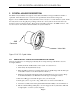


CHC-15 CRYSTAL HOLDER & GC-15 GLASS CELL
2.2 1 INCH DIAMETER CRYSTALS
INFICON pioneered the standard AT-cut, 5 MHz, 1-inch diameter crystals for use in liquid applications.
The
AT-cut quartz is chosen for its superior mechanical and piezoelectric properties, and the angle of cut
can be
adjusted to obtain a zero temperature coefficient at a desired operating temperature. The 1 inch
dia
meter was chosen to allow enough distance between the active area of the crystal and the mounting o-
ring.
This improves the overall stability of the crystal by reducing the frequency changes due to
mounting stress.
2.2.1 ELECTRODE CONFIGURATION
Figure 5 below shows INFICON’s 1” crystal electrode patterns. The left figure shows the ½ inch diameter
front electrode (al
so called sensing electrode) with an extended electrode that wraps around the edge of
the cr
ystal and extends into a semicircle shown in the top half of the right figure. The lower half of the
right figure shows the ¼ inch diameter rear electrode (also called contact electrode).
This configuration enables both electrical contacts to be
made on the backside of the crystal allowing
measurement in conductive liquids.
The oversized front electrode (½ inch in dia
meter as oppose to the ¼ inch diameter rear electrode) was
cho
sen to ensure a more consistence deposition across the active area of the crystal. The exposed area of
the front electrode is 0.212 i
n
2
(137 mm
2
), but the active oscillation region (displacement area) is limited
to the overlapping area of the front and rear electrodes (0.053 i
n
2
or 34.19 mm
2
).
Figure 5NNN 1-Inch Diameter Crystals – Electrode Configuration
Page 7