
Datasheet


Data Sheet 4 Rev. 1.02, 2009-12-10
IFX24401
Pin Configuration
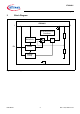
3 Pin Configuration
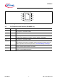
Figure 2 Pin Configuration PG-TO252-5 (top view)
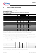
3.1 Pin Definitions and Functions (PG-TO252-5 )
Pin Symbol Function
1I Input
Connect ceramic capcitor between I and GND
2N.C.No Connect
May be open or connected to GND
3GNDGround
Internally connected to heat slug
4ENEnable Input
Low signal level disables the regulator. Pull-down resistor is integrated.
5QOutput
Place capacitor between Q pin and GND. Capacitor placement should be close to pin.
Refer to capacitance and ESR requirements in “Functional Range” on Page 6
Heat Slug -- Heat Slug
Connect to board GND and heatsink
INC ENQ