
Datasheet


IFX24401
General Product Characteristics
Data Sheet 7 Rev. 1.02, 2009-12-10
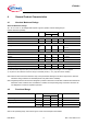
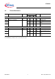
4.3 Thermal Resistance
Pos. Parameter Symbol Limit Value Unit Conditions
Min. Typ. Max.
IFX24401TEV50 (PG-TO252-5, )
4.3.1 Junction to Case
1)
1) not subject to production test, specified by design
R
thJC
– 4 – K/W measured to pin 5
4.3.2 Junction to Ambient
1)
R
thJA
– 115 – K/W Footprint only
2)
2) EIA/JESD 52_2, FR4, 80 × 80 × 1.5 mm; 35µ Cu, 5µ Sn
4.3.3 – 57 – K/W 300mm
2
heatsink area on
PCB
2)
4.3.4 – 42 – K/W 600mm
2
heatsink area on
PCB
2)
IFX24401ELV50 (PG-SSOP-14)
4.3.5 Junction to Case
1)
R
thJC
– 7 – K/W measured to pin 5
4.3.6 Junction to Ambient
1)
R
thJA
– 120 – K/W Footprint only
2)
4.3.7 – 59 – K/W 300mm
2
heatsink area on
PCB
2)
4.3.8 – 49 – K/W 600mm
2
heatsink area on
PCB
2)