
Datasheet

Data Sheet 4 Rev. 1.02, 2010-05-20
IFX25001
Pin Configuration
3 Pin Configuration
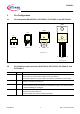
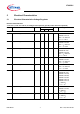
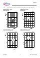
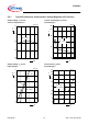
3.1 Pin Assignment PG-SOT223-4, PG-TO252-3, PG-TO263-3, and PG-TO220-3
Figure 2 Pin Configuration (top view)
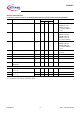
3.2 Pin Definitions and Functions PG-SOT223-4, PG-TO252-3, PG-TO263-3, and
PG-TO220-3
4
Pin No. Symbol Function
1IInput
connect Input pin to positive DC voltage source (e.g. battery);
a small filter capacitor connected close to the Input pin and GND is recommended
2GNDGround
internally connected to heat slug pin
3QOutput
connect a capacitor close to the Output pin and GND according to the values specified
in “Functional Range” on Page 5
4 / Heat Slug GND Heat Slug
internally connected to GND pin;
connect to heatsink to improve thermal performance
3*72YVG
,
*1'
4
*1'
3*72YVG
, *1' 4
*1'
3*72YVG
,
*1'
4
*1'
6276&YVG
,
*1'
4
*1'