
Installation Sheet

4
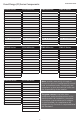
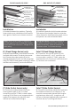
Note: Installer must verify all rough-
in dimensions prior to installation
and consult local and national codes.
Conformity and compliance to local and
national codes are the responsibility of
the installer.
Tenga en cuenta: Instalador debe
comprobar todas las dimensiones en las
partes previa a la instalación y consultar
localmente y nacionalmente los códigos.
La conformidad y el cumplimiento de
códigos local y nacional es responsabilidad
del instalador.
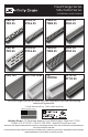
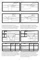
Drain can be adjusted upward
for an additional ½” in height.
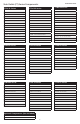
Drain can be adjusted upward
for an additional ½” in height.
Section A-A
FFED 25, FFDG 25,
FFMN 25, FFAS 25
Section A-A
FFED 65, FFDG 65,
FFMN 65, FFAS 65
Section A-A
FFTIF 65
Section A-A
FFAS 125
1¹⁄
¹⁶
"
¹³⁄
¹⁶
"
1"
2¼"
3"
1¹⁄
¹⁶
"
¹³⁄
¹⁶
"
2½"
2¼"
3"
1³⁄
¹⁶
"
¹³⁄
¹⁶
"
2½"
2"
⅜"
2¼"
3"
1¹⁄
¹⁶
"
4¹³⁄
¹⁶
"
¹³⁄
¹⁶
"
3¼"
3"
Side Outlet (FT) Series:
Section B-B
FTED 25, FTDG 25,
FTMN 25, FTAS 25
Section B-B
FTED 65, FTDG 65,
FTMN 65, FTAS 65
Section B-B
FTTIF 65
1¹⁄
¹⁶
"
1"
2¼"
2⅞"
1¹⁄
¹⁶
"
2½"
2¼"
2⅞"
1³⁄
¹⁶
"
2½"
2"
⅜"
2¼"
2⅞"
Fixed Flange (FF) Series: