
Installation Sheet

6
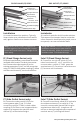
Limited waste pipe access:
Measure the distance from the top of the
existing waste line to the top of the suboor.
Ensure that the outlet section (D) is at
minimum of 2” less than this dimension,
cut the 3” length of the outlet section (D) if
necessary. DO NOT remove more than 2” from
the outlet section. Determine the distance
from the bottom of the outlet section (D) to
the top of the existing waste pipe (F). Cut a 2”
PVC or ABS pipe to a length 1/8” less than this
dimension. Bond the 2” PVC/ABS pipe to a 2”
DWV PVC/ABS coupling using PVC/ABS primer
and cement. Connect the other end of the 2”
PVC/ABS pipe to the outlet section (D) via a 2”
DWV no hub rubber coupling. Bond the free
end of the 2” pipe and coupling assembly to
the existing waste pipe using PVC/ABS primer
and cement.
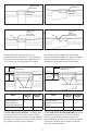
3. Spread a mortar bed across the intended
shower area and ensure the drain channel
(C) is level. Back ll region under the channel
ange so that pitch begins level to the edge of
the stainless steel channel (C). Pitch this bed
one plane towards the drain body.
4. When mortar layer is dry, perform
necessary waterproong (liquid membrane or
fabric sheet membrane) as per local code and
manufacturers’ instructions. Paint or bond
waterproong directly to the channel’s ange.
5. After waterproong is completely dry, lay
thinset and nishing material. Finish material
on to the channel ange. DO NOT allow tile to
nish over the depth of the channel.
Límite acceso de tubería de residuos:
Medir la distancia desde la parte superior
de la línea de residuos existentes a la parte
superior del subsuelo. Asegúrese que la
sección de salida (D) este mínimo 2” menos de
la dimensión, corte 3” de largo de la sección
de salida (D) si es necesario. NO REMUEVE
más de 2.5” de la sección de salida. Determine
la distancia desde debajo de la sección de
salida (D) a la parte superior de la tubería
existente (F). Corte un tubo de PVC o ABS a 2”
a lo largo 1/8” menos de la dimensión. Una la
2” de tubería de PVC/ABS a 2” DWV PVC/ABS
de acoplamiento usando PVC/ABS primer y
cemento. Conecte la otra parte de 2” de tubería
PVC/ABS a la sección de salida (D) vía a 2” DWV
sin ningún acoplamiento elástico. Una la parte
nal de la 2” de la tubería y la asamblea de
acoplamiento a la existencia de la tubería de
residuos usando PVC/ABS primer y cemento.
3. Extienda mortero a través del baño
previsto y asegure que el canal (C) este
anivelado. Rellene la región baja del canal
para que comience a brear a nivel del borde
del canal de acero (C). Bree esto a un plano
hacia el drenaje.
4. Cuando el motero este seco, realice la
necesaria impermeabilización (Membrana de
liquidó o membrana de tejido) según las reglas
locales y las instrucciones del fabricante. Pinte
o enlace la impermeabilización directamente
al reborde del canal.
5. Después de que la impermeabilización se
seque por completo, colocar el thinset y el
material terminado. El material terminado
hasta el borde del canal. NO PERMITA o DEJE
que el tile termine encima de la profundidad
del canal.
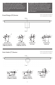
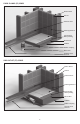
Note: When oor pitch is needed to begin
at a zero level, determine the length of
the channel (B) less the 1” ange around
it’s perimeter. Cut a hole in the suboor to
the measured dimensions at the desired
location. Place the ST65/ST125 Placement
Brackets (Optional Component) in the newly
created hole and screw into suboor. Recess
the stainless steel channel (C) into the
suboor and bracket. Allow the 1” ange to
sit onto the suboor.
Tenga en cuenta: Cuando el piso sea pitch
es necesario que comienza a un cero nivel,
determine la longitud del canal (B) menos de
1” alrededor del perímetro. Corte un agujero
en el subsuelo a la dimensión medida de la
ubicación deseada. Colocar el ST65/ST125
soportes de colocación (Componentes
Opcionales) en el recién agujero y atornille en
el subsuelo. Empotrar el canal de acero (C)
en el subsuelo y soporte. Permita el 1”brida
que este sentado en el subsuelo.