ecoSchwank-X IL-X Gas-Fired Luminous (High Intensity) Infrared Heaters INSTALLATION / OWNER’S MANUAL WARNING Improper installation, adjustment, alteration, service or maintenance can cause property damage, injury or death. Read the installation and operating and maintenance instructions thoroughly before installing or servicing this equipment. Not approved for use in any residential application. SAFETY ALERT: This heater must be installed and serviced only by a trained gas service technician.
NOTICE: This manual is current for this product. Occasional revision of the product Certification Standard may require changes to the product and/or this manual. This publication, or parts thereof, may not be reproduced in any form, without prior written consent from The Manufacturer. Unauthorized use or distribution of this publication is strictly prohibited.
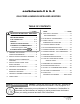
ecoSchwank-X & IL-X GAS FIRED LUMINOUS INFRA-RED HEATERS TABLE OF CONTENTS TOPIC ......... PAGE TOPIC ……...PAGE IMPORTANT INFORMATION - READ FIRST 9. GAS SUPPLY & PIPING ................................ ..14 APPLICATION ............................................. 4 GAS CONVERSION ....................................... 14 HEATER EXPANSION................................. 5 10 ELECTRICAL & THERMOSTAT ...................... 15 GAS CONNECTION............................... 5, 14 VENTING ..........
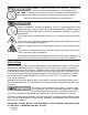
IMPORTANT Installer: Present this manual to the end user. Acquaint the end user with Important Information: Cover & pages 4 to 8. END USER: In particular you must be aware of ‘Clearances to Combustible’ requirements and the limitations of stacking or placing material near the heaters. Make your safety personnel and staff aware of this information. WARNING Improper installation, adjustment, alteration, service or maintenance can cause property damage, injury or death.
WARNING Heater Expansion It is a normal condition that during heat-up and cool-down a radiant heater will expand and contract. Allowances for heater expansion must be made in the gas connection and heater suspension. Improper installation, alteration, or adjustment can result in property damage, injury or death. WARNING Gas Connection Improper installation, connection, or adjustment can result in property damage, toxic gases, asphyxiation, injury or death.
WARNING Clearance to Combustibles Location of flammable or explosive objects, liquids or vapors close to the heater may cause fire or explosion and result in property damage, injury or death. Do not use, store or locate flammable or explosive objects, liquids or vapors in proximity of the heater. The clearance to combustible material represents the minimum distance that must be maintained between the outer heater surface and a nearby surface.
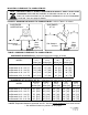
MOUNTING CLEARANCE TO COMBUSTIBLES NOTE: FOR AREAS USED TO STORE COMBUSTIBLE MATERIAL A ‘PEEL & STICK’ SIGN IS SUPPLIED: USE INDELIBLE MARKER TO RECORD VALUES ‘H’, ‘S’, ‘F’, & ‘B’. POST THE SIGN ADJACENT TO THE HEATER THERMOSTAT OR IN A PROMINENT LOCATION. See next page for details. FIGURE 1: MINIMUM DISTANCES TO COMBUSTIBLES - refer to Table 1 for values SUSPENDED HORIZONTALLY SUSPENDED AT 30° A A B F S S Site distance to floor = T C Max. Stack Height: ‘H’ = T - C Site distance to floor = T Max.
The clearance to combustible materials represents the minimum distance that must be maintained between the heater and a nearby surface. The stated clearance to combustibles represents a surface temperature of 90F° (50C°) above room temperature. It is the installer’s responsibility to ensure that building materials with a low heat tolerance which may degrade at lower temperatures are protected to prevent degradation.
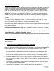
1. GENERAL APPLICATION A gas-fired radiant heater may be installed for heating of commercial / industrial non-residential spaces. It is beyond the scope of these instructions to consider all conditions that may be encountered. Installation must conform with all local building codes or, in the absence of local codes, with the National Fuel Gas Code, ANSI Z223.1/NFPA 54 in the U.S.A. or the Natural Gas and Propane Installation Code, CSA B149.1 in Canada.
3. INSTALLATION IN COMMERCIAL GARAGES AND PARKING STRUCTURES Luminous (high intensity) radiant heaters are suitable for use in commercial garages when installed in accordance with the latest edition of the Standard for Parking Structures, ANSI/NFPA 88A, or the Standard for Repair Garages, ANSI/NFPA No. 88B, or the Canadian Natural Gas and Propane Installation Code, B149.1.
6. MOUNTING CLEARANCES This heater must be mounted with at least the minimum clearances between the heater and combustibles as shown in FIG-1, TABLE 1, Page 7. The clearances to combustible material represent a surface temperature of 90 F° (50 C°) above ambient. It is the installer’s responsibility to ensure that building materials with a low heat tolerance which may degrade at lower temperatures are protected to prevent degradation.
FIGURE 3: SUGGESTED LAYOUT FOR COMFORT Y Long axis always level X Z Z X X Short axis may rotate up to 30° TABLE 2: SUGGESTED LAYOUT / MOUNTING DISTANCES FOR COMFORT* SUSPENDED HORIZONTALLY: (long axis level) MODEL TYPICAL ABOVE FLOOR TYPICAL BETWEEN HEATERS TYPICAL BETWEEN ROWS ecoSchwank-X 6 - IL-X 25 ecoSchwank-X 10 - IL-X 37 ecoSchwank-X 13 - IL-X 50 ecoSchwank-X 18 - IL-X 75 ecoSchwank-X 26 - IL-X 100 12’ (366 cm) 15' (460 cm) 16' (490 cm) 19' (580 cm) 22' (670 cm) 18' (550 cm)
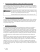
8. VENTILATION WARNING Inadequate venting of a heater may result in asphyxiation, carbon monoxide poisoning, injury or death. Heating system venting must be in accordance with all local, state, provincial, and national codes (ANSI Z223.1/NFPA 54 in USA; B149.1 in Canada). This heater is approved for unvented (indirect venting) application.
9. GAS SUPPLY PIPING WARNING Install and connect gas lines in accordance with local, state, provincial and national codes (ANSI Z223.1/NFPA 54 in USA; B149.1 in Canada). Incorrect installation and connection of gas lines may results in fire, explosion, property damage, injury or death Do not install any gas piping or wiring in the heat zone directly above the heater. Do not subject heater controls to leak test pressures when checking the main supply piping. A.
GAS SUPPLY PRESSURE: The maximum supply pressure must be limited to 14 inches w.c. (0.51 psi). If the line pressure is above 14 inches w.c. then a separate pressure reducing regulator must be used - follow all codes. The minimum pressure at the inlet to the heater regulator must be equal to or greater than 6.0 inches w.c. for NG and 11 inches w.c. for LP.
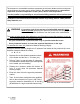
11. INSTALLATION A. Properly size and install ventilation as per Section 8, gas supply as outlined in Section 9, previous page, and electrical supply as per Section 10 above. B. Ensure adequate clearance around air openings into the combustion chamber C. Suspended infrared heaters shall be fixed in position independent of gas and electric supply lines. Hangers and brackets shall be of non-combustible material. Heaters subject to vibration shall be provided with vibration-isolating hangers.
FIGURE 6: ATTACH SUSPENSION HARDWARE 1. Suspension Hardware: Ensure hardware is sufficient to support the weight of the heater - see Figure 7 & Table 4 for heater dimensions #10 Jack Chain or heavier gauge #2 Lion Chain or heavier gauge ‘S’ Hooks 3/8” rod with bolt and nuts Other suitable brackets / hardware 2. Insert open Jack Chain link or ‘S” hook from the outside edge through the top hole at each end and each side of the heater body.
FIGURE 7: DIMENSIONS: ecoSchwank-X & IL B 12 1/2” (31.75 cm) TABLE 4: DIMENSIONS / WEIGHT / CAPACITY A Inches [cm] B Inches [cm] C Inches [cm] WEIGHT lbs [kg] GAS TYPE 14.25” [36.2] ecoSchwank-X 10 / IL-X 37 21.75" [55.2] ecoSchwank-X 13 / IL-X 50 28.75" [73.0] ecoSchwank-X 18 / IL-X 75 39.75" [101] ecoSchwank-X 26 / IL-X100 54.25" [137.8] 23” [58.4] 30.5” [77.5] 37.5” [95.3] 48.5” [123.2] 63” [160] 11” [27.9] 18.3” [46.5] 25.5” [64.8] 36.5” [92.7] 51” [129.5] 22 [10] 26 [11.8] 31 [14] 38 [17.
12. LIGHTING INSTRUCTIONS A Open the isolation valve in the main gas line and turn gas control knob on the combination gas valve to the “ON” position. B Switch on electrical circuit by turning the thermostat to the highest temperature setting. C The heater should attempt ignition and remain lit within thirty seconds. Note that the corresponding exhaust fan is operating properly. D If ignition does not occur, then cut off electrical power by turning the thermostat to off position.
14.
15.
16. SERVICE GUIDE WARNING Improper installation, adjustment, alteration, service or maintenance can cause property damage, injury or death. Read and understand this installation and operation manual thoroughly prior to assembly, installation, operation or service to this appliance. This heater must be installed and serviced only by a trained gas service technician. Do not store or use gasoline or other flammable vapours and liquids in the vicinity of this or any other gas fired appliance.
17. TROUBLESHOOTING GUIDE SET THERMOSTAT TO CALL FOR HEAT IS THE HEATER BURNING? THE SYSTEM STOP. YES IS WORKING PROPERLY. NO →CHECK FOR DARK SPOTS OR LINES ON THE TILE SURFACE →’DARK’ AREAS REPRESENT CRACKS OR BLOCKAGE OF THE TILE →SEE ’SERVICE’ SECTION 15 IS THERE LINE VOLTAGE (120V) OR 24 VOLTS TO THE THERMOSTAT CONTROL? →CHECK CIRCUIT BREAKERS OR FUSE →CHECK ON/OFF SWITCH →CHECK NIGHT TIME SET BACK CONTROL →CHECK FOR PROPER GAUGE OF WIRE →(24V) CHECK CONTROL CENTER TRANSFORMER.
IS THERE VOLTAGE (24V) TO IGNITION CONTROL MODULE FROM TRANSFORMER ? NO YES →CHECK ELECTRICAL CONNECTION FROM TRANSFORMER TO IGNITION CONTROL MODULE. →CHECK PROPER DISTRIBUTION WIRE GAUGE →ENSURE LOW VOLTAGE WIRES ARE PROPERLY INSTALLED, WIRING POLARITY IS CRITICAL →CHECK VA RATING ON THE TRANSFORMER. 40 VA FOR 1ST HEATER + 20 VA FOR EACH ADDITIONAL HEATER IN THE ZONE.
→CHECK ELECTRICAL WIRES FROM IGNITION IS THERE VOLTAGE FROM IGNITION CONTROL TO COMBINATION GAS VALVE? CONTROL TO COMBINATION GAS VALVE →CHECK IGNITION CONTROL, REPLACE IF NO NECESSARY YES IS GAS COMING THROUGH ORIFICE ON THE HEATER? →ENSURE ALL GAS VALVES ARE OPEN NO YES →CHECK SPARK IGNITER FOR CRACKS, DOES THE IGNITION CONTROL TERMINATE THE SPARKING PROCESS AFTER THE HEATER IS OPERATING? REPLACE SPARK IGNITER IF NECESSARY →ENSURE THE SENSING WIRE IS SECURELY CONNECTED TO THE SENSING PROBE →CL
18. HIGH ALTITUDE INSTALLATION This heater not to be installed at altitude above 6,800 feet. USA: The factory installed orifice for this appliance is approved for altitudes zero to 2000 feet above sea level. When installed above 2000 feet, refer to information below. Canada: The factory installed orifice for this appliance is approved for altitudes zero to 4500 feet above sea level. When installed above 4500 feet, refer to information below.
19. SEQUENCE OF OPERATION FOR HONEYWELL S87C DSI CONTROL 1. On a call for heat the S87C DSI Control will check for a false flame condition / short to ground. The module will lock out if a false flame condition is present. (Reset is usually done from the Thermostat manually). 2. Spark (30,000 volts) is generated at the spark igniter, for direct ignition of the main burner.
21. COMMISSIONING REPORT THIS APPLIANCE HAS BEEN FACTORY TESTED PRIOR TO SHIPMENT. HOWEVER, IT IS NOT A “PLUG-IN” APPLIANCE AND REQUIRES FIELD ADJUSTMENT AND COMMISSIONING TO ENSURE SAFE AND EFFICIENT OPERATION. A QUALIFIED GAS SERVICE TECHNICIAN MUST COMMISSION THE APPLIANCE AND COMPLETE THE COMMISSIONING REPORT. CONFIRM THAT THE APPLIANCE IS INSTALLED ACCORDING TO ALL LOCAL AND NATIONAL CODES AND THE INSTRUCTIONS IN THIS MANUAL.
TOLUMINOUS BE COMPLETED BYCOMMISSIONING THE LICENSED INSTALLER: HEATER REPORT HIGH INTENSITY COMMISSIONING REPORT TYPE OF GAS: NG LP LP DOES BUILDING HAVE A NEGATIVE CONDITION: YES NO NO WILL HEATER BE EXPOSED TO WELDING FUMES: YES NO NO IS HEATER EXPOSED TO CHEMICAL OR CORROSIVE ATMOSPHERE: YES NO NO IS AN OPEN FLAME COMPATIBLE WITH THE INSTALLED LOCATION: YES NO NO MINIMUM CLEARANCES CONFORM AS PER I&O MANUAL: YES NO NO Feet IF THIS IS A HIGH ALTITUDE AREA WHAT IS THE ALTITUDE ABOVE S
22. OPTIONAL ACCESSORIES PART # JL-0772-XX Line Voltage Thermostat TruTemp Thermostat Senses and averages ambient and radiant temperatures for true comfort control of IR systems Automatic unoccupied setback of 9°F (5°C) - can be overridden JM-0150-XX FOR SECURITY TO PREVENT UNAUTHORIZED OPENING: 2 - Stainless Steel Tamper Proof Screws for TruTemp Thermostat, including 1 Tool.
Flexible Gas connector 1/2” x 24” JL-0771-XX Pressure Equalizer Venturi Cover For drafty locations (near overhead doors, etc) JO-0368-XX Control Center / Transformer Relay JM-0300-XX AT72D-40VA Transformer for single heater JL-0776-XX Transformer Size Heaters Serviced 100 VA Transformer up to 4 JL-0778-XX 150VA Transformer up to 6 JL-0779-XX 200 VA Transformer up to 9 JL-0780-XX 250 va transformer up to 11 JL-0781-XX 350 VA Transformer up to 16 JL-0781-AA 500 VA Transformer up t
23.
23.
23.
LIMITED WARRANTY CERTIFICATE GAS-FIRED INFRA-RED LUMINOUS SERIES: ECOSCHWANK ECOSCHWANK-X / IL/ IL-X SERIES SERIES The Manufacturer warrants that this product is free from defects in material or workmanship under normal use and service subject to the terms of this document.