
User's Manual
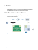
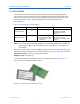
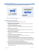
Table Of Contents
- Contents
- 1 Overview
- 2 DC and AC Characteristics
- 3 Electrical Interface
- 4 SPI Interface and Sequences
- 5 Power States
- 6 Messaging Protocol
- 7 microNode Provisioning
- 8 Antenna Diversity
- 9 Regulatory Considerations
- 10 Manufacturing Considerations
- 11 Errata
- Appendix A Abbreviations and Terms
- Appendix B PCB Land Pattern and Vias
- Appendix C REACH AND RoHS Compliance
- Appendix D On-Ramp Wireless RMA Process
- Appendix E microNode Mechanical Drawing

microNode Integration Specification Contents
On-Ramp Wireless, Inc. v 014-0033-00 Rev. H
10 Manufacturing Considerations ........................................................................ 47
10.1 Mechanical Outline................................................................................................................. 47
10.2 Host PCB Constraints ............................................................................................................ 47
10.3 Handling Procedures for microNode ...................................................................................... 47
11 Errata ................................................................................................................. 48
Appendix A Abbreviations and Terms ................................................................. 49
Appendix B PCB Land Pattern and Vias .............................................................. 51
Appendix C REACH AND RoHS Compliance....................................................... 52
Appendix D On-Ramp Wireless RMA Process .................................................... 53
Appendix E microNode Mechanical Drawing ...................................................... 54
Figures
Figure 1. On-Ramp Total Reach Wireless Network ......................................................................... 1
Figure 2. microNode (Top and Bottom Views) ................................................................................. 2
Figure 3. Typical Application Diagram ............................................................................................. 3
Figure 4. microNode Deep Sleep Power Consumption (mW Power vs VBATT Input) ................... 7
Figure 5. RX State Power Consumption (mW Power vs VBATT Input) .......................................... 8
Figure 6. microNode1: TX Power Consumption at 20.8 dBm (mW Power vs VBATT Input) .......... 8
Figure 7. microNode2: TX Power Consumption at 23.3 dBm (Watts Power vs VBATT
Input) .......................................................................................................................................... 9
Figure 8. SPI Timing, CPOL = 0, CPHA = 0 .................................................................................. 17
Figure 9. microNode Power-up Timing Sequence ......................................................................... 18
Figure 10. Host-Initiated microNode Wake Sequence – SRDY Low (Synchronous) .................... 19
Figure 11. Host-Initiated microNode Wake Sequence – SRDY High (Asynchronous) .................. 20
Figure 12. Host-Driven Reset Sequence ....................................................................................... 21
Figure 13. Host MRQ Release/microNode Allowed to Sleep Sequence ....................................... 22
Figure 14. microNode Oscillator Calibration: Current (Amps) vs Time (Seconds) ........................ 24
Figure 15. Representative Current Consumption During Deep Sleep, Idle, RX, and TX;
x16 Spreading Factor (Amps vs Seconds) .............................................................................. 26
Figure 16. SPI Master and Slave Message Sequences ................................................................ 29
Figure 17. Host Interface SPI Bus State Machine ......................................................................... 30
Figure 18. SPI Timing Example ..................................................................................................... 31
Figure 19. Host Message on SPI – MMsg Pair .............................................................................. 32