
User Guide
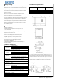

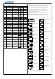
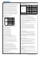
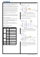
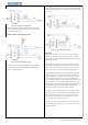
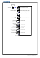

Table 1: Product models and specifications
●Never disassemble, refit and repair this product, or touch the inner components
by yourself, otherwise, there will be risk of electric shock, spark or malfunction.
●If the replay was serving beyond its estimated lifetime, there will be risk of
contact fusion and burning. It’s a must to always pay attention to the using
environment of relay, and using the relay within its rated load and estimated
lifetime. The estimated lifetime of the relay varies according to the output
●Panel size: DIN(48×48mm)
●Compatible with various temperature sensors (K, S, Wre, T, E,
J, B, N, CU50, PT100)
●Wide control temperature range: -50 - 1300ºC ( type K thermocouple)
●Display and control accuracy: 0.1 ºC,
high measuring precision: ±0.2%FS
●PID control mode with high-performance self-tuning function
●User-defined output and alarm modes
●Adjustable digital filtering for reducing external interference
●Self-calibration available for ensuring long term stability of the instrument
●high luminance LED screen with height 0.39“ characters,
anti-dazzle panel, well visibility
● Inbuilt switching power supply applicable for wide voltage range with
low power consumption
3.1 Insert temperature controller into the mounting hole in the panel, then put
on the fixer from the rear and hold it temporarily, make sure there is no gap
among temperature controller, panel and fixer. After that, fix the temperature
controller with attached two bolts of the fixer under torque of 0.29N to 0.39N.
3.2 Make sure the surrounding temperature is within the stipulated
temperature range, especially when there are two or more temperature
controllers.
AC/DC 12-24V
3.Diagram and installing size (unit: mm)
Figure 3: Panel Cutout
ITC-100VH
SSR control output
AC 100-240V
ITC-100RH
Relay control output
AC 100-240V
ITC-100RL
Relay control output
Storing temperature
2.Models and specifications
Model
Control output
Voltage
Figure 2: Mounting Bracket
Figure 1: Shell Size
ITC-100VL
SSR control output
AC/DC 12-24V
Weight
About 140g
Relay output: AC 250V 3A (resistive load)
Alarm output
Figure 4:Wiring diagram
Working temperature
Working humidity
-25 - 65ºC (No ice or moisture condensation)
■Safety warning
About 3W (12V - 24VDC)
85 to 100% of the rated voltage
About 5VA (100V - 240VAC)
About 4VA (12V - 24VAC)
●It’s a must to use this product within its specification and using scope.
load and switching condition.
●When power on, do not connect, disassemble and touch terminals, as those
may cause damage due to spark, malfunction or electric shock.
●No metal fragment, wire thread or metal dusts produced during installation
are allowed to be inside the device, otherwise, there will be risk of electric
●Please do not use this product in flammable and explosive locations,
■ Product features
Voltage output (for driving SSR): 12VDC, 30mA DC
Maximum load: 600Ω
Power
Working voltage
±0.2%FS 0.1ºC(<1000ºC); 1ºC(≥1000ºC)
0.5 seconds
0-50ºC
Relay output: AC 250V 3A (resistive load)
Control output
Relay output: AC 250V 3A (resistive load)
AC 100-240V 50/60Hz
AC/DC 12-24V 50/60Hz
DC 12-24V
PV: high luminance LED screen with 4 digits of height
9.9mm displayed in red
SV: high luminance LED screen with 4 digits of height
8.0mm displayed in green
Sampling period
Display accuracy
Characters
Temperature
compensation
Electrical endurance of relay: 100,000 times
Rated Voltage
shock, fire or malfunction.
otherwise, there will be risk of damage caused by explosion.
1.Technical parameters
RH 35-85%
-10 - 55ºC (No ice or moisture condensation)
4.Wiring diagram
2
© 2015 Inkbird Inc. All rights reserved.
www.ink-bird.com, CS@ink-bird.com