
User Guide

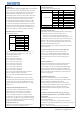
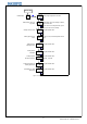

6.7 Parameters setting 6.6 Workflow for setting
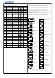
Table 2: parameters setting and definition After instrument powered on and run self-inspection, press “SET” key for
over 2 seconds to enter parameters setting mode. User can press “︽”
key(or “︾” key) to set the value. After value set, press “SET” key to
confirm and go for setting for another function. Then repeat above
operation, till all the functions are configured OK.Quit setting mode,
and enter PV/SV monitoring mode.
Attentions: if parameters were changed during parameters setting mode,
the temperature controller will save the change if there is no further
operation for over 10 seconds, and return to PV/SV monitoring mode.
dLAL:Deviation high
alarm
dF:Return difference
SC:Revise displayed
value
oP1: Output mode
Opl:Low limit of output
Oph:High limit of output
CtrL:Control mode
ALP:Alarm definition
CF:System functions
selection
HIAL:Alarm value for
high limit
LOAL:Alarm value for
low limit
dHAL:Deviation high
alarm
diH:Displayed value for
low limit
Parameter
Definition
HIAL
Upper alarm limit
LoAL
Lower alarm limit
0
dHAL
Deviation high alarm
dLAL
Deviation low alarm
dF
Hysteresis band
1
9999
500
Control mode
CtrL
none
0
2
1
9600
See 6.8.1
0~9999
1℃
3
See 6.10.2
0: On/OFF
See 6.8.3
0.3
120
0
0~31
2:Heater
0~220
0
-199~+999
1℃
2: Sel-turning
-9999
40
0~3
1~120
1~9999
1:0-10mA
4
0/2:time proportioning
-1999~+9999
1: automatic
2: No manual
0~220
0~20
3:Cooler
0~9999
-1999~+9999
0~42
0~999
M50
Integral Time
P
Differential
t
0: manual
Hysteresis time
Ctl
Control period
Sn
Input sensor
diP
decimal point position
diL
Displayed value for low
limit
diH
Displayed value for high
limit
SC
Sensor Calibration
LOC
Baud
dl
Opl
Low limit of output
Oph
High limit of output
ALP
Alarm definition
Digital filtering
Addr
See 6.10.1
Communication address
Communication baud
rate
1%
0~63
0~4800
100
See 6.8.4
See 6.9.5
See 6.10.1
See 6.10.1
See 6.8.2
1%
0
0
2
second
0.01S/℃
1 Digital
See 6.13
1 Digital
See 6.9.4
EP1 ~EP8
8 definitions for field
parameter
See 6.11.4
See 6.9.1
See 6.9.2
See 6.9.3
See 6.9.3
Select Any
Parameters from it
See 6.12.1
See 6.12.2
second
1000
0
Output mode
oP1
System functions
selection
CF
Automatic/Manual
status
run
Permission of revising
parameter
diP:decimal place
diL:Displayed value for
low limit
See 6.11.3
See 6.14
See 6.11.2
See 6.11.3
Value range
Unit
0~9999
See 6.8.1
-1999~+9999
9999
See 6.8.1
0~9999
0~200.0
1℃
0.1℃
1000
-1999~+9999
Remarks
See 6.8.1
Default
9999
1℃
Addr:Communication
address
1,3: PID
0.1℃
Figure 6:Workflow for setting
t:Hysteresis time
Ctl:Control period
Sn:Input sensor
M50:Integral Time
P:Rate
Baud:Communication
baud rate
dl:Digital filtering
run:Running status
LOC:Permission of
revising parameter
EP1-EP8:8 definitions
for field parameter
Press 3S
to enter Setting
Mode
SET
SET
SET
SET
SET
SET
SET
SET
SET
SET
SET
SET
SET
SET
SET
SET
SET
SET
SET
SET
SET
SET
SET
SET
SET
SET
4
© 2015 Inkbird Inc. All rights reserved.
www.ink-bird.com, CS@ink-bird.com