
User Guide


7.4 Solenoid valve or relay control 8. Field application example
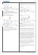
For example, the application of instrument for oven. Following example is based
on ITC-100RH and ITC-100VH, the required temperature is 150 ºC, and the high
limit is 160ºC.
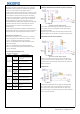
ITC-100RL is generally used for low voltage devices. It’s a must to pay
attention to whether the power supply voltage and alarm voltage is within
Figure 13:ITC-100RH Wiring diagram
the stipulated range when wiring.
7.5 Control load via external contactor (24V)
Figure 14:ITC-100VH Wiring diagram
Wiring steps:
1. Connect sensor: the sensor in figure 13 and 14 are both three lines RTD
sensors. Their connection method are the same. Red wire is for COM3,
other two blue wires are for COM4 and COM5 (two blue wires can exchange
COM port with each other).
2. Connect alarm: ITC-100RH and ITC-100VH’s alarm control output are the
ITC-100RL’s control mode is the same as figure 9. Please note that the same. COM12 is the power input port for alarm, which should connect with
power supply for heater is high voltage(120VAC), the power supply for phase line (L). COM11 is alarm control output port, which should connect
instrument is 24VAC (low voltage). with alarm. The other line of the alarm should connect with the null line.
3. Connect heating tube: ITC-100RH controls heating tube by its internal relay.
COM7 of the instrument connect with the power input port, which should
connect with phase line (L). COM8 is the control output port, which should
connect directly with the heating tube. The other wire of the heating tube
should connect with null line (N); TC-100VH output DC12V voltage as control
signal, driving SSR to control heating tube. COM8 of the instrument output
positive voltage, which should connect with SSR’s positive pole; COM6 of the
instrument output negative voltage, which should connect with SSR’s
negative pole. The polarity should not be inversely connected.
4. Connect power supply: the power supply port of the instrument are COM9
and COM10, which are for the phase line and null line respectively. A dual
linked switch should be connected in front of power supply, and connect
fuse in phase line(L). The wire used must be able to bear the load current,
otherwise, there will be risk of accidents such as fire
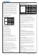
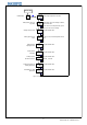
For simple users, no need to master all instructions, as long as the parameters
of the following parameters in the process to set up to get the ideal control effect,
set up flow chart as below:
Figure 11:ITC-100RL Wiring diagram
Figure 12:ITC-100RL Wiring diagram
8
© 2015 Inkbird Inc. All rights reserved.
www.ink-bird.com, CS@ink-bird.com