
Installation Manual

SIFER Reader Add-on for EliteX/PrismaX. Installation Manual. SIFER Reader Add-on for EliteX/PrismaX. Installation Manual.
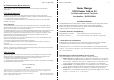
Retaining Tabs (x2)
Beeper
CAUTION !
Take care not to damage the PCB
surfaces or exposed components.
Optical Tamper Sensor
LAN Connections
4-way
socket.
SIFER board
4-pin header
SIFER Reader board
Hook & Loop Dots
(Underneath Reader board)
Hole for retaining screw
Parts List
- SIFER Reader PCB assembly. - 2 pairs of Self-adhesive Hook & Loop dots.
- Installation Manual (This document)
Specifications
Power Supply Input: From host Terminal.
Operational Current: 30mA in addition to the current already drawn by the Terminal.
Installation
Refer to drawing on page 3.
If the Terminal is already installed:
a) Disable LAN Comms & Tamper monitoring for the Terminal prior to commencing.
b) Separate the Terminal from its backplate. See Step 1 below.
c) Disconnect the power, LAN and any other cabling taking care not to short any of the
wires. See the Terminal’s Installation manual and relevant system manual/s for details.
1. a) Remove the retaining screw at the bottom of the case if fitted.
b) Separate the front and rear (backplate) halves of the case by first applying gentle pressure
to the two lower locking tabs in the bottom rear of the case with a small flat-blade screwdriver,
while gently pulling the lower front of the case away from the rear.
c) Next, gently pull the lower front of the housing clear of the backplate then lift upwards
to release the upper locking tabs.
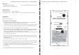
2. Attach two of the white Hook & Loop dots to the main PCB in the locations shown in the
drawing opposite. Attach two of the transparent dots in the corresponding locations on the
SIFER Reader board.
NOTE: PrismaX is shown for reference. EliteX is very similar.
3. Keeping the Reader board on a slight angle to prevent the Hook & Loop Dots from making
contact, connect the SIFER Reader board 4-pin header into the socket on the Terminal,
then gently press the board down so that the Hook & Loop dots make contact.
NOTE: When connected, it is normal for a gap of ~1mm to exist between the black parts of
the connectors.
4. Install/Re-install the Terminal as described in the Terminal’s installation manual.
Retaining Slots
32