
Installation Manual


InnoSenT sets standards – worldwide
Page 3 Version 1.0 USER MANUAL IPM-224_F
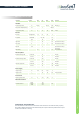
Interface
1 not connected
2 not connected
3 V
CC
input supply voltage
4 GND input analog ground
5 IF1 output signal 1
6 not connected
Pin # Descripon In / Out Comment
CONFIDENTIAL AND PROPRIETARY
The informaon contained in this document shall remain the sole and exclusive property
of InnoSenT GmbH and shall not be disclosed by the recipient to third pares without prior
consent of InnoSenT in wring.
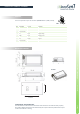
Mechanical Outlines
azimuth
3D-View
PIN 1
The sensor provides a 6 pin JST connector (06FMN-BMT-A-TF, SMD, vercal)