
User Manual

Item Part No.
Meso-H, isolated 70MEH00001
Meso-HX, isolated (ATEX) 70MEHX0001
Meso-HX, isolated (FM, CSA) 70MEHX1001
Meso-L 70MEL00001
Software and cable
HART PC modem RS232 70MEM00001
HART PC modem USB 70MEM00003
Software CD 70CDSOFT01
Accessories
Surface mounting box 70ADA00008
Rail mounting box 70ADA00009
Head mounting kit 70ADA00012
Rail mounting kit 70ADA00013
DATA (shortform)
CONNECTIONS
ORDERING TABLE
MESO-HX Ex-DATA
Approval Demko 03 ATEX 134077X
II 1G Ex ia IIC T4/T5/T6
Control Drawing 88DRW00053
Approval FM, J.I. 6D9A4.AX, CSA 2007 Certicate 1863602
Class I, II and III, Division 1, Group A, B, C, D and G
Control Drawing 3-7967
Output (current loop)
U
i
: 30 VDC
I
i
: 100 mA
P
i
: 900 mW
L
i
: 1 mH
C
i
: 1 nF
MESO-HX must be powered from an certied isolating power supply or
zener barrier, placed outside the hazardous area. MESO-HX shall be
mounted in an Ex-compatible housing having protection IP20 or better.
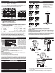
INPUTS
Fig 9.
Power supply
1)
: Meso-H 10 - 42 VDC
2)
Meso-L 11 - 42 VDC
2)
Meso-HX 12 - 30 VDC/max 100 mA/0.9W
1)
When communicating acc to HART the load must be more than 250 ohm.
2)
Supply voltage over 36V demands at least 250 ohm´s load
Load
Load
Load
Meso-H
Meso-L
1. Power supply, load and output signal are connected according
to gure above
2. Input signal is connected according to one of the gures 1-9
CABLE LENGTH
To calculate maximum
length of the cable for
reliable communication,
add load resistance and
approximated cable re-
sistance. Please note that
the loop resistance for
reliable communication
must be in the range 230
– 1100 Ohm, 250 Ohm is
a commonly used value.
In the data-sheet for the cable you get the cable capacitance/meter. Use the
R value you calculated and the cable capacitance/meter together with the
diagram above to get the maximum length of the cable. For multidrop mode,
use the formula below.
The cable length can also be calculated according to the formula:
L = 65*10
6
/ (R * C) – (Cn*5000 +10 000) / C
Where:
L: is the cable length (m)
R: is load resistance (including resistance of barrier)+cable resistance (ohm)
C: is cable capacitance/m (pF/m)
Cn: is the number of Meso transmitters in the loop.
L can also be changed to ft, if so C is given in pF/ft.
For Ex-version MESO-HX also the restrictions on cable capacitance Ci
and inductance Li stated in the Certicates and Approval documents
must be observed. Also national and regional standards and regulations
must be consulted.
l
l
l
Meso-HX
Fig12
Fig10
Fig11
see ”Cable Length”
12-30 VDC
MESO-HX may only be
connected to transducers
complying with ”Simple
Apparatus” acc. to
EN 60079-11:2007 § 5.7
1)
1)
R
i
≤ 10 Ω
Ambient temperature:
T4: -40
o
C ≤ Tamb ≤ +85
o
C
T5: -40
o
C ≤ Tamb ≤ +65
o
C
T6: -40
o
C ≤ Tamb ≤ +50
o
C
Service temperature ≤ max ambient temperature
MESO-HX must be installed in an enclosure having
an Ingress Protection suitable for the actual use
but at least IP20.
If MESO-HX is mounted in a housing (head) made of light metals and
installed in hazardous area make sure the content of magnesium (Mg)
in the light metal is less than 6%.
If MESO-HX is mounted in a housing which is isolated from ground and
can be charged to an ignition capable level, then the housing shall be
electrostatically grounded when installed in hazardous area.
!