Operating Manual INSYS Modem INSYS Modem 336 4.1 INSYS Modem 56k 4.
Copyright © July 06 INSYS MICROELECTRONICS GmbH Any duplication of this manual is prohibited. All rights on this documentation and the devices are with INSYS MICROELECTRONICS GmbH Regensburg. Restrictions of guarantee This handbook contains a concise description. The compilation of the text has been made with the utmost care. Despite all efforts, there may be deviations compared with the actual functions. No guarantee can therefore be given for the accuracy of the contents.
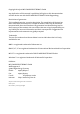
INSYS Modem 336/56k 4.1 (UL) July 06 Contents 1 SCOPE OF DELIVERY....................................................7 2 GENERAL.....................................................................7 3 NOTES REGARDING THE USE OF THE MANUAL ..........8 4 DESCRIPTION ..............................................................9 4.1 FRONT PANEL ............................................................................9 4.2 TOP ...................................................................
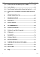
Contents 4 INSYS Modem 336/56k 4.1 (UL) 5.10 REMOTE SWITCHING AND REMOTE QUERY VIA DTMF....................34 5.11 ACCESS CONTROL ....................................................................36 5.12 DATA TRANSMIT CONTROLLER (IDLE CONNECTION CONTROL)..........38 5.13 PRIORITY CIRCUIT FOR MODEMS WITH PHONES CONNECTED IN SERIES 39 6 OPERATION WITH A PLC...........................................42 7 FIRMWARE UPDATE .................................................43 7.1 FLASHCOM.EXE ....
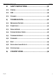
INSYS Modem 336/56k 4.1 (UL) July 06 Contents 12 SAFETY INSTRUCTIONS.............................................90 12.1 GENERAL ................................................................................90 12.2 SMS .....................................................................................90 12.3 CLEANING...............................................................................90 13 TECHNICAL DATA......................................................91 13.
INSYS Modem 336/56k 4.1 (UL) 1 Scope of Delivery Scope of Delivery Before you begin with the initial operation, please check if all accessories are included in the box. ¾ ¾ ¾ ¾ INSYS Modem 336 4.1, INSYS Modem 56k 4.1, or INSYS Modem 56k 4.1 UL 2 phone cords (TAE-N at RJ12 and RJ12 at RJ12), not for version UL. PC connection cable 9/9-pin (RS232 cable) User Guide In case the content is not complete please contact your supplier. Please also check the modem for shipping damage.
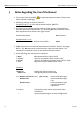
Notes Regarding the Use of the Manual 3 INSYS Modem 336/56k 4.1 (UL) Notes Regarding the Use of the Manual ¾ This manual uses the symbol will be marked accordingly. for especially important notes. Further notes ¾ All factory settings are marked “default”. Example (Chap. 5.7.3): Enter old password (default: QWERTY) ¾ In Chapters 4 to 6 the description consists of two columns. Individual functions are described on the left side.
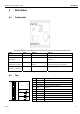
Description INSYS Modem 336/56k 4.1 (UL) 4 Description 4.1 Front panel The INSYS Modem 336/56k 4.1 (UL) has four LED’s to indicate the operating state.
Description 4.3 INSYS Modem 336/56k 4.
INSYS Modem 336/56k 4.1 (UL) 4.5 Description Configuration Software HSComm The configuration of the modem takes place via AT commands which are entered by a terminal program or a control program in the form of character sequences. For a simple set-up, all basic functions of the INSYS modem 336/56k 4.1 (UL) can be entered without knowing the individual commands and their parameters, using the configuration software. The software can be installed on all common Microsoft Windows operating systems.
Description 4.5.2 INSYS Modem 336/56k 4.1 (UL) Initial operation using HSComm 4.5.2.1 Serial interface Control/PC and the modem must be modulated via the following joint settings of the serial interface: ¾ Baud rate (Data transmission speed) ¾ Format (Start bit, data bits, parity, stop bits) ¾ Data flow control (Hardware/software handshake) PC Settings Serial interface settings of the PC (Interface menu) – the current settings are displayed in the message bar of the main window.
INSYS Modem 336/56k 4.1 (UL) Description DTR Behavior The signal Data Terminal Ready (DTR) on the serial interfaces indicates that the connected device (control, PC) is switched on, connected and ready for operation. The INSYS Modem 336/56k 4.1 (UL) may react to the device being switched off or the cable being removed. Echo With the setting Echo the modem sends each command back via the serial interface. During terminal operation, this makes it obvious which commands are entered.
Description INSYS Modem 336/56k 4.1 (UL) 4.6 Installation Instructions Note: For the installation of the INSYS modem with the configuration software HSComm, please also read Chapter 4.5. Important Safety Instructions When using the communication device and its accessories, the following safety instructions must be observed at all times to prevent fire, electric shock or personal injury. 1. 2. 3. The device may not be used in wet environments, damp rooms or close to water, e.g.
Description INSYS Modem 336/56k 4.1 (UL) Please observe our safety instructions. 1. Mounting on DIN rail 2. Connecting the power supply a) Connecting the ground connection b) Connecting the power supply 10..60V DC X1 3 3 10...60 VDC 4 4 GND 5 5 GND 6 6 Reset 7 7 GND 8 8 Input 1 9 9 Input 2 10 10 IN 2 2 IN 1 GND 2 Ext. Reset 1 Power supply 1 GND Note: The minimum value is 10V DC. The maximum value is 60V DC. 3. Switch on power supply 4.
Description INSYS Modem 336/56k 4.1 (UL) Open the terminal program and enter the command. When the message appears on your monitor, the device has been successfully installed. 8. AT Enter LED RXTX leuchtet kurz OK Check the communication using the configuration program HSComm Open the installed HSComm. The configuration program will automatically search for the connected modem. 9. Connection to the telephone network Connect the phone outlet and the modem with the supplied phone cord. 10.
Functions INSYS Modem 336/56k 4.1 (UL) 5 Functions This chapter describes the functions and settings of the INSYS Modem 336/56k 4.1 (UL). The settings can be selected and changed via AT commands, using any terminal program (Hyperterminal, TeraTerm, etc.) Alternatively, all common settings can also be comfortably performed via the configuration software HSComm (see Chapter 4.5 "Configuration software HSComm”).
Functions INSYS Modem 336/56k 4.1 (UL) Our example currently shows the settings from user profile 0.
Functions 5.1.2 INSYS Modem 336/56k 4.1 (UL) Save Configuration If the modem configuration was adjusted to certain user requirements, these settings can be saved in the user profiles 0 AT&W0 or 1. AT&W1 AT&W Configuration changes will be lost after a RESET or restart if they were not saved before. 5.2 Serial Data Transmission 5.2.
Functions 5.2.2 INSYS Modem 336/56k 4.1 (UL) Data Buffer for Serial Data Transmission The modem has a fast send and receive cache (so-called buffer) to adjust the modem to the operating speed of the application. It is, however, possible to deactivate this data buffering and switch to bit direct mode. When working with buffers, handshake is recommended to avoid transmission errors. 5.2.
Functions INSYS Modem 336/56k 4.1 (UL) 5.2.4 Hardware Data Flow Control with RTS/CTS Hardware Data Flow Control with the Modem (CTS). RS232 Cable Application CTS Line (E.g.: PC or control) Modem When the input buffer of the modem exceeds a certain fill state, the modem will set the CTS line to OFF. This indicates to the application not to send any data.
Functions 5.2.6 INSYS Modem 336/56k 4.1 (UL) Software data flow control XON and XOFF Send data Application XON or XOFF character (E.g.: PC or control) Modem When the input buffer of the modem exceeds a certain fill state, the modem will insert an XOFF character into the data stream to the application. This character will cause the application to send no more data. It will depend on the according application software if the RTS/CTS data flow control is supported.
INSYS Modem 336/56k 4.1 (UL) 5.2.8 Functions Dial-up delay The standard TBR21 applies to all public phone networks in EU countries (Belgium, Denmark, German, Finland, France, Greece, Great Britain, Ireland, Italy, Luxembourg, Netherlands, Austria, Portugal, Sweden, Spain), as well as in Switzerland, Liechtenstein, Norway and Iceland. According to the TBR 21 regulations, after 12 futile dial-up attempts each further dial-up is locked within 2 hours.
Functions 5.3.1 INSYS Modem 336/56k 4.1 (UL) V42 Error correction The V.42 error correction includes the protocols LAPM (Link Access Procedure for Modem) and MNP 4. LAPM is the preferred error correction. MNP 4 is supported for compatibility reasons with other MNP modems. Both methods determine frames to transfer net data and use CRC (Cyclic Redundancy Check) check sums for error tests. In V.42, the possibility exists to have the modem identify if the partner is a V.
Functions INSYS Modem 336/56k 4.1 (UL) 5.4.1 5.4.2 V.42bis data compression Switch on V.42bis data compression. AT%C3 Switch off V.42bis data compression AT%C0 V.42bis data compression may only be performed for a V.42 connection (LAP-M or MNP 4). First of all, V.42bis generates a so-called dictionary for the data compression, which contains frequently used character sequences.
Functions 5.5 INSYS Modem 336/56k 4.1 (UL) Selective Call Answer Not for INSYS Modem LL. If the selective call acceptance is activated, the modem will only accept calls from certain callers. The identification of permitted callers takes places via the caller ID transmission (CLIP). This must, however, be supported by the phone system or the exchange connection, where the modem is connected to.
Functions INSYS Modem 336/56k 4.1 (UL) The list of phone numbers may also contain wildcards “'*”. This allows the activation of entire blocks of phone numbers. The wild card character (“*”) replaces exactly 1 character of the phone number. AT*N=94158692** Our example will activate all phone numbers that start with 94158692** and have 2 more digits (e.g.: an extension). AT*N6=94158692** The phone number may not contain separators such as brackets or space characters.
Functions INSYS Modem 336/56k 4.1 (UL) Configuration with HSComm: 5.7 Alarm Input (Not for the leased line version) 2 X1 3 3 10...60 VDC 4 4 GND 5 5 GND 6 6 Reset 7 7 GND 8 8 Input 1 9 9 Input 2 10 10 IN 2 2 IN 1 GND Ext. Reset 1 Power supply 1 GND The INSYS Modem has two digital inputs which are activated by connecting them to ground (at least 4 seconds). When an alarm occurs, the INSYS modem can send a message either via a data connection, a fax or an SMS.
Functions INSYS Modem 336/56k 4.1 (UL) The status of the alarm inputs can be queried by AT commands or via DTMF tones.
Functions INSYS Modem 336/56k 4.1 (UL) 5.8 Send Messages Not for INSYS Modem LL. Note: The sending time of an SMS from the sender to a recipient depends on the pertinent provider of the service number. Depending on the degree of utilization and the time of day, an SMS may be on the way for an extended period. 5.8.1 Transmission Configuration The modem can not only send the alarm message to another analogue modem, but also to a mobile phone as an SMS.
Functions INSYS Modem 336/56k 4.1 (UL) SMS to Mobile or Fixed Network Enter the service number of the network provider to send SMS, or the phone number for fax and data connections Definition of the variable alarm texts and phone number for the SMS dispatch. After this command is activated, the modem will query the alarm text.
Functions INSYS Modem 336/56k 4.1 (UL) 5.9 Remote Configuration (Remote Control) 5.9.1 Mode of operation Modem 1 Phone line (local modem) Modem 2 (remote modem) To switch into the remote configuration mode, a data connection must be established between the modems. A particular connection type is not mandatory. However, we recommend using only error-corrected connections for the remote configuration, to avoid transfer errors for the commands.
Functions INSYS Modem 336/56k 4.1 (UL) 5.9.4 Start of the remote configuration at the local modem Dial the remote modem, e.g. an INSYS modem ATD The modem will establish a successful connection Connect… Switch to the mode “Remote Configuration” **** Prompt for entering the password Remote Access Remote Password: Enter password (default) QWERTY If the entry was successful, the remote modem will send the input prompt > 5.9.
Functions 5.10 INSYS Modem 336/56k 4.1 (UL) Remote Switching and Remote Query via DTMF Not for INSYS Modem LL. In phone networks, DTMF is used to dial a remote terminal. To enable switching centers to distinguish between voice and DTMF digits, these digits are created from two unique frequencies, which cannot be created by people in this form. These tones are created with the keys of fixed network and mobile phones.
Functions INSYS Modem 336/56k 4.1 (UL) 5.10.2 Operation After the message ”OK” (short low tone – short pause – short high tone), the modem expects the input of the PIN. If the modem recognizes the dial tone of a modem that wants to establish a connection, it will immediately switch to data mode.
Functions 5.11 INSYS Modem 336/56k 4.1 (UL) Access Control Not for INSYS Modem LL. 5.11.1 Password To protect you from unauthorized access via the phone line, the modem may be protected by a password. This password is used to establish a data connection, as well as for security callback and remote configuration AT*C OLD PASSWORD QWERTY NEW PASSWORD The default setting is QWERTY. Confirm 5.11.2 Data Connection An incoming connection is only released after the caller has entered the password.
Functions INSYS Modem 336/56k 4.1 (UL) The deactivation takes place by deleting the call back phone number. 5.11.3.2 Operation Establishing a connection to the remote modem by entering the AT command. The connection to the modem is established. The modem responds to an incoming call. You must now enter the “Remote Password”, which is identical to the password for the remote configuration.
Functions 5.12 INSYS Modem 336/56k 4.1 (UL) Data Transmit Controller (Idle Connection Control) Not for INSYS Modem LL. The Data Transmit Control (DTC) is a function integrated in the firmware which monitors the data transmission in online mode. This function prevents the modem to stay online for an unlimited amount of time, although no data is being transmitted anymore. 5.12.1 Activation The activation takes place in the registry S15, and any time period between 1 and 255 seconds may be set.
Functions INSYS Modem 336/56k 4.1 (UL) 5.13 Priority Circuit for Modems with Phones Connected in Series Not for INSYS Modem LL. The INSYS Modem 336/56k 4.1 (UL) gives a phone connected in series priority, to make sure it interferes as little as possible with the usage of the phone connection. Command AT-STE=0 AT-STE=1 AT-STE=2 AT-STE=3 AT-STE=4 AT-STE=5 AT-STE=6 AT-STE=7 Function 1 (Chap. 5.13.1 ) == √ == √ == √ == √ Function 2 (Chap. 5.13.2) Function 3 (Chap. 5.13.
Functions INSYS Modem 336/56k 4.1 (UL) 5.13.2 Going off-hook on account of a telephone connected in series If a telephone connected in series goes off-hook during an existing modem connection, the modem will immediately terminate the connection. The telephone is connected to the line and receives a dialing tone. In the registry S86, the value is set to 25. When the phone connection is terminated, the modem will not establish a new connection.
Functions INSYS Modem 336/56k 4.1 (UL) 5.13.3 Remote Terminal Connection Abort When the remote terminal aborts a connection, the modem will immediately hang up. In the registry S86, the value is set to 25. Changing the loop voltage to detect the function – Remote Terminal Connection Abort (U3) – can be set with the help of AT commands. ATS86=25 AT-TTE=U1, U2, U3 Voltage Loop voltage after the connection is terminated.
Operation with a PLC 6 INSYS Modem 336/56k 4.1 (UL) Operation with a PLC Not for INSYS Modem LL. The INSYS Modem 336/56k 4.1 (UL) has been tested for the most common PLC systems on the market. The documentation (Application Notes) of the settings required for the respective PLC can be queried at INSYS MICROELECTRONICS (E-mail: insys@insys-tec.de). HSComm offers a range of recommended settings for the modems connected at the PLC or the PC at the control center.
Firmware Update INSYS Modem 336/56k 4.1 (UL) 7 Firmware Update 7.1 Flashcom.exe This function enables the firmware update of the INSYS Modem 336/56k 4.1 (UL) without switching the EEPROM. The new version is available from your service partner. Query of the used firmware ATI4 Unpack the file into any directory and start Flashcom.exe. The program will automatically search for the connected modem.
Firmware Update INSYS Modem 336/56k 4.1 (UL) Select the according INSYS Modem and start the update. Close the window after the update is completed. 7.2 Terminal Program As an alternative to the procedure described in the previous chapter, the firmware update may also be performed via a terminal program. 7.2.1 Requirements For the firmware update you will need a PC and a terminal program. The terminal program must be able to perform an ASCII upload (ASCII data transmission protocol).
Firmware Update INSYS Modem 336/56k 4.1 (UL) 7.2.2 Activation and Process Start of the flash update AT** The modem sends a response Download initiated… The update is performed in two steps. Transfer file with the help of a terminal program. ¾ ASCII upload of the file HS_LADER.S37 Download Flashcode ¾ ASCII upload of the firmware (xxxxxxxx.S37) Device successfully programmed Completion of the loading procedure. The process is finished.
AT Command Set 8 INSYS Modem 336/56k 4.1 (UL) AT Command Set Most of the INSYS communication devices are controlled internally via AT commands. A terminal program is integrated in the HSComm. The AT commands can be directly entered at the menu item “Terminal”. Alternatively, we recommend the terminal program TeraTerm by T. T. Teranishi. The free software can be downloaded at http://www.vector.co.jp/authors/VA002416/teraterm.html.
AT Command Set INSYS Modem 336/56k 4.1 (UL) 8.1 Overview AT Commands Command Description AT** Start of the flash load function ATA Answer mode The modem is switched into response mode. This is only effective in Germany, if the connected phone goes off-hook or if a call comes in. A/ Repeat the last command The last command is repeated. AT\A Select maximum MNP block size Define maximum block size for error corrected MNP transmissions.
AT Command Set INSYS Modem 336/56k 4.1 (UL) Command Description AT\B Send “break” to the other modem For connections that were not error corrected the modem sends a break signal to the other modem. The length of the signal is: the specified parameter times 1/10 of a second. For error corrected connections, the modem sends a break signal according to the active error correction protocol without considering a parameter specification.
AT Command Set INSYS Modem 336/56k 4.1 (UL) Command Description AT*C1 PIN for remote switching via DTMF This PIN secured the functions when the alarm inputs are remotely switched via SMS and for remote query of the alarm inputs. AT&C OLD PIN Requires the old PIN (default: 1234). Wrong input leads to ERROR. NEW PIN Enter the new PIN (4 characters) CONFIRM Repeat the new PIN Wrong input leads to ERROR. OK The PIN is immediately stored in the EEPROM.
AT Command Set INSYS Modem 336/56k 4.1 (UL) Command Description AT+CPIN? Dummy command for GSM compatibility AT+CPIN? responds with "+CPIN: READY". Note: This command only serves for the purpose of compatibility with applications for GSM devices. AT+CREG? Dummy command for GSM compatibility AT+CREG? responds with "+CREG: 0,1". Note: This command only serves for the purpose of compatibility with applications for GSM devices. AT+CSQ Dummy command for GSM compatibility AT+CSQ responds with "+CSQ: 20.
AT Command Set INSYS Modem 336/56k 4.1 (UL) Command Description ATD Dial The modem goes off-hook and dials according to the dialing string transmitted via the ATD command. After it dialed, the modem attempts to establish a connection. If the ATD command was performed without a dialing string, the modem goes off-hook and attempts to connect to the other modem (without dialing). The behavior of the modem depends on the activation of the line current recognition (see ATX command).
AT Command Set INSYS Modem 336/56k 4.1 (UL) Command Description ATD ‚ Dial tone delay: The modem performs a dial tone delay before it executes the next character of the parameter string. The delay length is defined in the S8 registry. L Last number re-dialing. ; Return to the input mode after dialing. It is added to the end of the dialing string and causes the modem to return to the entry mode when it reaches “;” (with: message OK).
AT Command Set INSYS Modem 336/56k 4.1 (UL) Command Description AT&D DTR (CT108/2) behavior DTR (CT108/2) behavior - Monitoring on/off transitions of the RS232 DTR line of the PC. AT\D AT&D0 DTR is ignored. Allows the operation with PCs which do not run DTR. AT&D1 A DTR on/off transition causes the modem to react as if it had received an abort sequence +++. The modem switches to the input mode without hanging up. AT&D2 A DTR on/off transition causes the modem to hang up.
AT Command Set INSYS Modem 336/56k 4.1 (UL) Command Description AT\D Acoustic response Description (Continuation) short long tone – short pause - short high tone OK ready,command executed, PIN ok long low tone ERROR invalid command, wrong PIN high long tone LOW HIGH Alarm input active Alarm input inactive If no DTMF tone is entered for more than 25 seconds, the modem will automatically disconnect.
AT Command Set INSYS Modem 336/56k 4.1 (UL) Command Description AT+GCI= Set country code The command AT+GCI allows the customization of the modem for different countries. As default, the modem is set to Europe (CTR21) with AT+GCI=FD. Currently, the modem is only authorized for this country profile. Note: ATH Please note that all country settings will result in ALL modem settings being reset to the default settings (such as AT&F&W).
AT Command Set INSYS Modem 336/56k 4.1 (UL) Command Description AT&K Select data flow control between the PC and the modem (handshake) Fax operation default is RTS/CTS. AT-K AT&K0 No data flow control AT&K3 Select data flow control RTS/CTS (default) AT&K4 Select data flow control XON/XOFF AT&K5 Select transparent data flow control XON/XOFF AT&K6 Select RTS/CTS and XON/XOFF data flow control AT&K8 Activates the controlled half duplex operation on the serial interface for RS485.
AT Command Set INSYS Modem 336/56k 4.1 (UL) Command Description AT\K Break control The modem reacts to a break (receive path OFF for a certain amount of time), which it receives from another modem or from the PC, or from the command AT\B according to the parameters. July 06 1.
AT Command Set INSYS Modem 336/56k 4.1 (UL) Command Description ATL Speaker volume This command regulates the speaker volume (see command ATM). AT%L ATL1 Speaker volume low (default) ATL2 Speaker volume medium ATL3 Speaker volume high Display level of the received signal The value that is reported from the modem equals the already amplified level within the modem, not the phone line level.
AT Command Set INSYS Modem 336/56k 4.1 (UL) Command Description AT+MR= Show modulation type The command AT+MR= enables the display of the modulation type after the message CONNECT AT+MR=0 Switches the display function OFF (default). AT+MR=1 Switches the display function ON. The displayed value applies to the sent data. AT+MR=2 Switches the display function ON. The displayed value applies to the received data.
AT Command Set Command INSYS Modem 336/56k 4.1 (UL) Description AT+MS=, [Automode], [Send Minbaud, Send V92 Maxbaud], [Receive Minbaud, Receive MaxB103 baud] (Continuation) B212 V.90 56000, 54667 ,53333 ,52000, 50667, 49333, 48000, 46667, 48000, 46667, 45333, 42667, 41333, 40000, 38667, 37333, 36000, 34667, 33333, 32000, 30667, 29333, 28000 V.
AT Command Set INSYS Modem 336/56k 4.1 (UL) Command Description AT*M Remote terminal selection Defines the protocol that is used to send the alarm string to the network provider. AT*M0 The remote terminal is a normal fixed network modem (default) AT*M1 The remote terminal is a mobile phone with network access via PET/IXO/TAP protocol and data format 8N1 (e.g.
AT Command Set INSYS Modem 336/56k 4.1 (UL) Command Description AT*N= Permitted numbers for selective call acceptance Definition of 8 authorized phone numbers, for which modem access is permitted. Only if the transmitted phone number matches a phone number that was entered in the list will the modem report RING for an incoming call or will accept the call according to the settings of ATS0 (the line RI is activated with each call, irrespective of that fact).
AT Command Set INSYS Modem 336/56k 4.1 (UL) Command Description AT*P Password query AT*P0 Switches the password query off after the connection has been established. (default) AT*P1 Switches the password query on after the connection has been established. If the password query is activated, the modem will query the password after CONNECT has taken place. After the password has been entered correctly, the actual CONNECT will take place and data may be transmitted.
AT Command Set INSYS Modem 336/56k 4.1 (UL) Command Description AT\Q Quiet Call Quiet Call will switch of the phone connected in series at the first ring. In connection with the selective call answer (AT&N), calls from a previously defined phone number can take place without a ring of the phone connected in series. If the phone number is not detected by the modem, the phone is switched on again after the first ring. AT\Q0 AT\Q1 AT\Q2 Switches Quiet Call off (default) Activates Quiet Call.
AT Command Set INSYS Modem 336/56k 4.1 (UL) Command Description AT%S Ability to switch between DCD and DSR lines AT&S AT%S0 The DSR signal is on the DSR line The DCD signal is on the DCD line (default) AT%S1 The DSR signal is on the DCD line The DCD signal is on the DSR line (Interchangeability of the lines) DSR behavior This command determines how the modem treats its DSR (CT107) output. AT&S0 AT&S1 AT*S DSR always ON (default).
AT Command Set INSYS Modem 336/56k 4.1 (UL) Command Description AT-STE= Priority Circuit for Modems with Phones Connected in Series The INSYS Modem 336/56k 4.1 (UL) gives a phone connected in series priority, to make sure it interferes as little as possible with the usage of the phone connection. (see Chapter 5.10) Monitoring Functions: 1) Detecting a busy phone line During a dial-up attempt, the model detects the busy phone line. (LINE IN USE).
AT Command Set INSYS Modem 336/56k 4.1 (UL) Command Description AT-TTE=U1, U2, U3 Parameter configuration for priority circuit The command AT-TTE=U1, U2, U3 will set the change of the loop voltage. The settings are required to detect AT-STE=. (see Chap. 5.
AT Command Set INSYS Modem 336/56k 4.
AT Command Set INSYS Modem 336/56k 4.1 (UL) Command Description AT&V Show the configurations AT&V0 The active configuration of the modem, the saved user defaults and the saved phone numbers 0 to 3 (the parameter 0 may be omitted) are displayed. AT&V1 Displays the diagnostic data of the last connection (connection partner, reason for disconnect). TERMINATION REASON: Reason for connection termination. E.g.
AT Command Set INSYS Modem 336/56k 4.1 (UL) Command Description AT+VCID= Set CLIP With this function, the phone number of the caller can be displayed during an incoming call. (Only for phone lines or systems that support CLIP. If you want to use the CLIP function, please ask your network provider, if your connection supports this function.
AT Command Set INSYS Modem 336/56k 4.1 (UL) Command Description ATX Extended result messages, dial tone detection The command determines which group of messages the modem sends to the PC. This is important for PBXs, as often a leading 0 or 9 must be dialed before a dialing tone is heard on the line. Blind dialing (dialing without detecting the dialing tone) is activated or deactivated according to the parameter.
AT Command Set INSYS Modem 336/56k 4.1 (UL) Command Description ATZ Software reset The command causes the modem to perform a software reset. The modem will load the default saved by the user (according to the parameter). If no parameter is specified, the user default 0 is loaded. AT&Z ATZ0 Software reset; afterwards the user default 0 is loaded. ATZ1 Software reset; afterwards the user default 1 is loaded. Save phone numbers The command saves four entries permanently in the EEPROM.
AT Command Set INSYS Modem 336/56k 4.1 (UL) 8.2 Overview Fax and Voice Commands More detailed information regarding the Fax Class 2 commands and a document regarding voice commands can be obtained from your supplier. 8.3 AT Messages List of message numbers and messages texts depending on the command ATX.
AT Command Set 74 INSYS Modem 336/56k 4.
AT Command Set INSYS Modem 336/56k 4.
S Registry 9 INSYS Modem 336/56k 4.1 (UL) S Registry S registries may be read and written using the ATS command. (See Chapter 8 “AT Command Set”, command ATS) Certain S registries may only be read; into others only a particular range of values may be entered. If the range of values is exceeded, the modem will report OK, although the value was not accepted. We therefore recommend to immediately check modifications by reading (ATS?).
S Registry INSYS Modem 336/56k 4.1 (UL) Register Function Units Range Default S30 Time until hang-up for inactivity 10 s 0-255 0 S31* General settings - 192 S36* Resetting the error protocols - 135 S38 Time until forced hang-up s S39* Flow control - 3 S40* General settings - 104 S41* General settings - 195 S46* Data compression - 138 S48* Settings for V42 negotiation phase - 7 S86 Error result code - read only S91* Send level - S95* Result code - 9.
S Registry INSYS Modem 336/56k 4.1 (UL) S4 Linefeed character Linefeed character S5 Backspace character Backspace character S6* Waiting period dial tone Maximum waiting time for the dialing tone. After the modem went off-hook it waits 7 seconds for the dialing tone (fixed for approval purposes). If it detects a dialing tone during this waiting period it will start dialing.
S Registry INSYS Modem 336/56k 4.1 (UL) S13* Number of dialing attempts to send the message Bit Meaning Bit 0 – 3 Number of dialing attempts Bit 4 - 7 Reserved Range of values:1...12 Default value: 3 S13 determines the number of attempts to send the message. Note: The limitation to a maximum of 12 attempts is necessary for approval purposes (black listing).
S Registry INSYS Modem 336/56k 4.1 (UL) S21* Settings for V24 Bit Meaning Bit 0.1 Reserved Bit 2 CTS behavior CT106 (CTS) behavior: 0: see AT\K0 1: see AT&R1 Bit 3-4 DTR behavior CT108 (DTR) behavior: 0: see AT&D0 1: see AT&D1 2: see AT&D2 3: see AT&D3 Bit 5 DCD behavior CT109 (DCD) behavior: 0: see AT&C0 1: see AT&C1 Bit 6 DSR behavior CT107 (DCD) behavior: 0: see AT&S0 1: see AT&S1 Bit 7 Reserved Reserved S22* Speaker system settings 80 Bit Meaning Bit 0.
S Registry INSYS Modem 336/56k 4.1 (UL) S24* Time period until switching into sleep mode The time after which the modem switches to energy saving mode (sleep) during inactivity is determined (in seconds) in S24. The energy saving mode will be quit as soon as characters are sent to the modem, or when a call comes in. Note: When the modem is in sleep mode, it is necessary to send an “AT” command before sending other commands. This first “AT” command may not be answered with “OK”.
S Registry INSYS Modem 336/56k 4.1 (UL) S31* General settings Bit Meaning Bit 0 Reserved Bit 1 Description Connect message 0: 3-line message (\V0) 1: Expanded 1-line message (\V1) Bit 2-3 Error correction Messages Messages: 0: Only PC baud rate 1: PC and phone baud rate 2: Only phone baud rate Bit 4-7 (ATW1) (ATW2) Reserved S36* Reset of error logs Bit Meaning Bit 0..2 determines what happens if an attempt to establish a V.42 LAP-M connection fails. It is connected to the registry S48.
S Registry INSYS Modem 336/56k 4.
S Registry S46* INSYS Modem 336/56k 4.1 (UL) V.42bis Data Compression S46=136 No data compression S46=138 V.42bis data compression on S48* V.42bis Connection setup protocol S48=0 Only LAPM connection possible S48=7 LAPM or MNP 4 connection S48=128 Connection protocol as laid down in S36 S86 Error event code When a connection fails (NO CARRIER), an event code is written into this registry.
INSYS Modem 336/56k 4.1 (UL) S91* S Registry Transmit Level The value for the transmit level of the modem is stored in the S91 registry. The value can be set between 0 and 15. The connection can in some cases be improved by decreasing the transmit level. S91=0 Transmit level 0 dBm S91=15 Transmit level – 15 dBm Note: The range and the default value depend on the country settings (AT+GCI).
Sending of SMS as Fax or E-mail 10 INSYS Modem 336/56k 4.1 (UL) Sending of SMS as Fax or E-mail Chapter 11 shows an overview of network providers for German-speaking countries (Germany, Austria, and Switzerland). All necessary information is available from the customer service center of the provider.
July 06 Service center 01930100 43900664914 +41794998123 T-COM (Germany) A1 (Austria) Swisscom (Switzerland) E-mail address+space+text Text E-mail address 555 E-mail address+space+text SMS format 8000 Phone number abc@defg.de abc@defg.de E-mail address abc*defg.de This is a test This is a test abc*defg.de This is a test Example 10.2 Network provider INSYS Modem 336/56k 4.
FAQ INSYS Modem 336/56k 4.1 (UL) 11 FAQ In the following some questions are described, which – from experience – may occur during the installation. Problem: Possible cause: Remedy The modem does not accept calls. Automatic call acceptance is deac- Enter the following commands in tivated. the terminal program: ATS0=2 AT*A1 The key entries are not disThe display of the key entries played in the terminal program. (echo) is deactivated. Activate the echo with ATE1.
FAQ INSYS Modem 336/56k 4.1 (UL) Problem: Possible cause: Remedy It is not possible to establish a phone connection. The modem dials with the pulse dialing method instead of the required tone dialing method, or vice versa. You can determine if your phone system dials with pulses or tones: If you hear a rattling on the line during dialing, you are using pulse dialing. The dialing types can be switched with the commands ATDP or ATDT. See also Chapter 9 “AT Command Set”, commands ATDP,ATDT, ATP, ATT.
Safety Instructions INSYS Modem 336/56k 4.1 (UL) 12 Safety Instructions 12.1 General Please comply with these instructions! ¾ All areas that can be opened are maintenance areas. Unauthorized opening of a maintenance area and inappropriate repairs may endanger the user. ¾ The INSYS Modem 336/56k 4.1 (UL) may not be used in wet environments, damp rooms or close to water. ¾ The device should not be used during a thunderstorm, as this could result in electrical shock. ¾ The INSYS Modem 336/56k 4.
Technical Data INSYS Modem 336/56k 4.1 (UL) 13 Technical Data 13.1 Mechanical Features INSYS modem 336/56k 4.1 (UL) 13.2 Weight 8.82 oz Dimensions (maximum) w x d x h = 55 x 110 x 75 Temperature range 32°F..131°F Protection class Housing IP 40/ Terminal IP 20 Humidity 0 - 95% non-condensing Power Supply All specified technical data was measured with a nominal input voltage, full load, and an ambient temperature of 77 °F.
Technical Data INSYS Modem 336/56k 4.1 (UL) 13.
Technical Data INSYS Modem 336/56k 4.1 (UL) 13.5 Telephone Interface RJ 12 plug with nose to the back E W b2 b1 a2 a1 RJ 12 plug front Layout of the RJ12 Connector and the RJ45 Jack Pin Description Pin Description 1 NC 4 b1 2 a2 5 b2 3 b1 6 NC Meaning of the Signals: a1, b1: Incoming phone lines (e.g. exchange connection or PBX) a2, b2: they are used to connect a telephone in series. In idle state, a2 and b2 are connected with a1 and b1 via a loop current connector.
Technical Data INSYS Modem 336/56k 4.1 (UL) 13.6 Standards 13.6.1 ITU Standards (CCITT) ITU Standards (CCITT) Meaning V.21 Transmission with 300 bps (duplex) V.22 Transmission with 1,200 bps (duplex) V.22bis Transmission with 2,400 bps (duplex) V.23 Send with 75 bps and receive with 1,200 bps and vice versa V.23 half-duplex Send or receive with 1,200 bps (half duplex) V25bis Alternate command set for AT command set V.32 Transmission with 9,600 bps or (fallback) 7,200, 4,800 bps. V.
Technical Data INSYS Modem 336/56k 4.1 (UL) 13.7 Reset A reset is possible via the screw terminal marked Reset, using an external device. A low potential must be applied at the terminal for at least 3 seconds. Alternatively, the reset key should be pressed at least 3 seconds to trigger a reset. 13.8 Digital Inputs and Outputs 13.8.1 Alarm input LOW 0 .. 1 V HIGH 4 .. 12 V Input current from LOW to internal +5V: Type 0.5 mA 13.8.
Country Codes 14 INSYS Modem 336/56k 4.1 (UL) Country Codes Adjust the modem to local requirements using the command AT+CGI= All other settings should be carried out after the country code has been selected, because some factory settings depend on the country. INSYS modem 336/56k 4.
Country Codes INSYS Modem 336/56k 4.1 (UL) INSYS modem 336/56k 4.
Country Codes INSYS Modem 336/56k 4.1 (UL) INSYS modem 336/56k 4.
Country Codes INSYS Modem 336/56k 4.1 (UL) INSYS modem 336/56k 4.