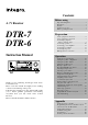
Contents Before using Important Safeguards ........................................ 2 Precautions ........................................................ 3 Features ............................................................. 4 Supplied accessories ......................................... 4 Before operating this unit ................................. 5 A / V Receiver DTR-7 DTR-6 Preparation Audio equipment connections .......................... 6 Video equipment connections ...........................
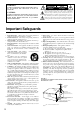
WARNING: TO REDUCE THE RISK OF FIRE OR ELECTRIC SHOCK, DO NOT EXPOSE THIS APPLIANCE TO RAIN OR MOISTURE. CAUTION: TO REDUCE THE RISK OF ELECTRIC SHOCK, DO NOT REMOVE COVER (OR BACK). NO USER-SERVICEABLE PARTS INSIDE. REFER SERVICING TO QUALIFIED SERVICE PERSONNEL.
Precautions 1. Warranty Claim You can find the serial number on the rear panel of this unit. In case of warranty claim, please report this number. 2. Recording Copyright Recording of copyrighted material for other than personal use is illegal without permission of the copyright holder. 3. AC Fuse The fuse is located inside the chassis and is not user-serviceable. If power does not come on, contact your Onkyo authorized service station. 4.
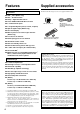
Features Supplied accessories Check that the following accessories are supplied with this unit. Key Features ■ THX*1 select (DTR-7 only) ■ DTS*2 decorder built-in ■ Dolby*3 digital decoder built-in ■ Linear PCM 96 kHz/24-bit D/A converter ■ 5.1 multichannel inputs AM loop antenna x 1 ■ 4 assignable digital inputs (2-coaxial, 2-optical) FM antenna x 1 (Connector shape may vary depending on where the unit is purchased.
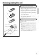
Before operating this unit Installing the remote controller batteries 1. Remove the battery compartment cover by pressing the tab and lifting up the cover. 2. Insert two AA (R6- or UM-3)-size batteries into the battery compartment. Carefully follow the polarity diagram (positive (+) and negative (–) symbols) inside the battery compartment. 3. After batteries are installed and seated correctly, replace the compartment cover.
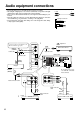
Audio equipment connections Audio connection cable • Do not piug in the power cord until all connections have been made. • On each pair of input jacks, a red connector (marked R) corresponds to the right channel, and a white connector (marked L) to the left channel. • Please refer to the instruction manual of each component when making any connections. • Insert the plugs and connectors securely. Remember that improper connection can result in noise, poor performance, or damage to the equipment.
Audio equipment connections 1. DIGITAL INPUT connectors • If your CD player has a digital output connector, connect it to a proper DIGITAL INPUT connector for clear and dynamic sound play. • This unit provides four digital input connectors to connect CD players, MD recorders, DAT decks, etc. having a digital output connector. When using these connectors, connect the unit also via the audio connection cables. You should also note that the signals you can record are analog signals only.
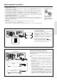
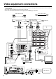
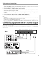
Video equipment connections • On each pair of input jacks, the red connector (marked R) corresponds to the right channel, and the white connector (marked L) to the left channel. • The yellow connector (marked V) is used for video connection. • Please refer to the instruction manual of each component when making any connections.
Video equipment connections 1. Digital audio connections This receiver has a powerful digital signal processor for use with DVD players, DAT decks, and CD players. The digital inputs, COAXIAL 1, 2 and OPTICAL 1, 2 can be assigned to individual input selector buttons, so when an input selector button is pressed, the assigned digital input is used instead of the corresponding analog input. (See page 23,29.) 2. Connect your second video cassette deck. 3.
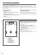
Connecting speakers The DTR-7/6 allows you to connect two speaker systems. Before connecting the speakers, place them correctly by consulting the instruction manuals that came with your speakers. For surround playback (see “Using the listening modes” on page 34), the configuration and placement of your speakers are very important. For Home THX cinema surround playback, we recommend that you use a THX speaker system that is certified by Lucasfilm Ltd. (such as Onkyo HTS SYSTEM-2).
Connecting speakers • This receiver is designed to produce optimum sound quality when speakers with impedances within the specified ranges are connected. Please check the following information and choose speakers with appropriate impedances for the connections. FRONT SPEAKERS: SURROUND SPEAKERS: CENTER SPEAKER: A or B: 6 ohms min./speaker 6 ohms min./speaker 6 ohms min.
Connecting speakers Connecting a subwoofer PRE OUT Use the PRE OUT SUBWOOFER jack to connect a subwoofer with a built-in power amplifier. If your subwoofer does not have a builtin amplifier, connect an amplifier to the PRE OUT SUBWOOFER jack and the subwoofer to the amplifier.
Connecting an equalizer The AMP IN and the PRE OUT FRONT connectors are attached with jumper plugs. When connecting an equalizer, remove these jumper plugs before connecting the audio connection cables. DTR-7 L R DIGITAL INPUT L R V FRONT SPEAKERS A SURROUND SPEAKERS S (DTR-7) AMP IN OUT FRONT COAXIAL 1 ANTENNA VIDEO-1 PRE OUT R IN FRONT COAXIAL 2 L R L 1. Remove the jumper plugs. See “Connecting power amplifiers.
Making antenna connections Outdoor antenna Indoor antenna Connecting the 300 ohm ribbon wire: Loosen the screws and wrap the wire around these screws. Then tighten the screws with a screwdriver. 300 ohms ribbon wire 1 2 3 ✦ ✦ ✦ ✦ ✦ ✦ ✦✦ ✦ ✦ ✦ 6 3 6 mm mm mm Slit B Connecting the antenna cable to the 75/300 ohm antenna adapter. (The antenna adapter must be separately ordered.) 15mm Wire A Connecting the coaxial cable: 1.
Making antenna connections Connecting the included antennas ANTENNA AM FM 75 Connecting the FM indoor antenna: The FM indoor antenna is for indoor use only. Extend the antenna and move it in various directions until the clearest signal is received. Fix it with push pins or similar implements in the position that will cause the least amount of distortion. If the reception is not very clear with the attached FM indoor antenna, the use of an outdoor antenna is recommended.
Using the on-screen display Using the OSD (on-screen display) function lets you display each screen on your TV so that you can perform various settings using only the remote controller. 1 2~4 How to use the on-screen display 1. Press the OSD MENU button. The on-screen display appears. 2. Press the upper or lower edge of the ENTER/Cursor button to select the item. The items you can select on each screen are shown on the next page. 3.
Using the on-screen display OSD screens Input Selector screen (page 27,32) ** Input Selector ** Input = DVD OPTICAL 1 Digital Input Setup Video Assign Setup IntelliVolume Setup Listening Dolby Mode= Pro Logic THX Cinema Select the input source (page 27). Perform digital input setting (page 29). Assign a video input source (page 40). Perform IntelliVolume setting (page 43). Set the listening mode (page 36).
Setting the speaker configuration Perform this setup before using the unit.
Setting the speaker configuration • Using the on-screen display 3 ** Speaker Setup ** Config Setup Distance Setup Level Setup Bass Peak Setup 4 * Config Setup * All Channel For THX Speakers =No 5 1. Press the OSD MENU button. 2. Select “Speaker Setup” and then press the right edge of the ENTER/Cursor button. 3. Select “Config Setup” and then press the right edge of the ENTER/Cursor button. 4. For the DTR-6, go to the next step. For the DTR-7, the display shows “All Channel For THX Speakers.
Setting the speaker distance 1 SP/SYS SETUP SPEAKERS Setting the distance from each speaker to the listening position (Loudspeaker Position Time Synchronization*) TUNED A AUTO PRESET/MODE ADJ PUSH TO ENTER 2~7 PRESET/MODE ADJ SPEAKERS A TUNED PCM DIGITAL FM STEREO AUTO ft PUSH TO ENTER PRESET/MODE ADJ PUSH TO ENTER 8 Select a value that is closest to the actual distance between each speaker and the listening position.
Setting the speaker Level 1 SP/SYS SETUP SPEAKERS Using the test tone to adjust the speaker output levels DSP A PRESET/MODE ADJ PUSH TO ENTER 2 PRESET/MODE ADJ SPEAKERS A STEREO PCM DIGITAL db PUSH TO ENTER Center PRESET/MODE ADJ Right Notes: • In order to correctly set the output levels, use a hand-held Sound Pressure Level meter (SPL), set to C-Weighting and Slow averaging. A Radio Shack® SPL meter (catalogue number 3302055) or equivalent can be used.
Setting the Speaker level 1 SP/SYS SETUP SPEAKERS Setting the bass peak level (Bass Peak Level Manager* DTR-7 only) DSP A PRESET/MODE ADJ PUSH TO ENTER 2 PRESET/MODE ADJ SPEAKERS A PUSH TO ENTER PRESET/MODE ADJ SPEAKERS A db To prevent damage to your subwoofer, you can set the bass peak level the subwoofer can reproduce. If your system does not include any subwoofer, this will set the bass peak level your Front speakers can reproduce. 1.
Setting the Speaker level • Using the on-screen display 3 * Bass Peak Setup * Bass Peak Level Limiter = Yes Peak Level =+18dB Starting The Test Tone 4 * Bass Peak Setup * 1.Turn Volume Up. 2.When Sound Distorts. 1. Press the OSD MENU button. 2. Select “Speaker Setup” and then press the right edge of the ENTER/Cursor button. 3. Select “Bass Peak Setup” and then press the right edge of the ENTER/Cursor button. The “Bass Peak Setup” screen appears.
Presetting FM/AM radio stations TUNING UP/DOWN FM MUTE/MODE CHARACTER/MEMORY FM MUTE/ MODE DIMMER DOWN TUNING CHARACTER/ MEMORY UP SP/SYS SETUP AUDIO ADJUSTMENT MASTER VOLUME BASS/ TREBLE STANDBY/ON PRESET/MODE ADJ STANDBY MULTI SOURCE UP DO W N MODE SMART SCAN CONTROLLER POWER SMART SCAN CONTROLLER PUSH TO ENTER ON OFF LISTENING MODE A SPEAKERS B DISPLAY DIRECT STEREO /DTS DSP THX REC OUT / MULTI SOURCE SURROUND DIGITAL/ ANALOG CH LEVEL MODE VIDEO4 MULTI CH INPUT PHONE
Presetting FM/AM radio stations Programming radio stations 1 SPEAKERS DSP TUNED A 1. Select the frequency that you want to store in the memory. (See Tuning in a radio station on page 24.) 2. Press the CHARACTER/MEMORY button. “Preset In? ” appears. 3. Press the SMART SCAN CONTROLLER. The “MEMORY” indicator lights up on the display. 4. Select the desired memory number using SMART SCAN CONTROLLER. 5. Press the SMART SCAN CONTROLLER. The received station will be stored in the specified preset number.
Selecting an input source 2. Make sure that the SPEAKERS A indicator is lit on the display. If it is not lit, press the SPEAKERS A button. 4. Adjust the sound volume to an appropriate level. Rotating the MASTER VOLUME control knob clockwise increases the sound volume. Rotating the MASTER VOLUME control counterclockwise decreases the sound volume.
Selecting an input source 2. SP A 1 SLEEP 2 MODE AUDIO 4. VOLUME ∆/∇ 1. INPUT SELECTOR 3 DIMMER 1 This button allows you to set the sleep timer. (See page 31.) 2 Press this button to set the mode in which you can operate the DTR-7/6. 3 Use this button to change the brightness of the display (normal or dim). 4 You can connect stereo headphones to the PHONES jack using a standard stereo plug.
Selecting an input source Setting the input signal format (Digital Input Setup) 1 DVD VIDEO-1 VIDEO-2 VIDEO-3 VIDEO-4 TAPE FM AM PHONO CD 2 DIGITAL/ ANALOG SPEAKERS TUNED A AUTO The input signal format defaults to “Automatic.” Although you can use this default setting normally, you may change it depending on the input signal format. Ex.) Setting the input signal format for DVD 1. Press the DVD input selector button. 2.
Selecting an input source • Using the on-screen display * Digital Input Setup * CD DVD VIDEO 1 :COAXIAL 1 Automatic :COAXIAL 2 Automatic :---Automatic 1. Press the OSD MENU button. 2. Select “Input Selector” and then press the right edge of the ENTER/Cursor button. 3. Select “Digital Input Setup” and then press the right edge of the ENTER/Cursor button. The “Digital Input Setup” screen appears. To display VIDEO 2 and later items, press the lower edge of the ENTER/Cursor button.
Selecting an input source Selecting the speaker system The DTR-7/DTR-6 can connect to two speaker systems. You can switch between the two speaker systems by using the SPEAKERS A and B buttons. Selecting Speaker system A (SPEAKERS A indicator appears.) Press the SPEAKERS A button to turn on or off the speakers connected to the FRONT SPEAKERS A, CENTER SPEAKER and SURROUND SPEAKERS terminals.
Selecting an input source Muting the sound (Muting function, remote controller only) Use this function to turn off the playback sound immediately. For example, you can use it when you receive a phone call when listening to music. Remote controller Press the MUTING button. The display shows "Muting." Now the sound output to the speakers and headphones stops. Press the MUTING button again to turn on the sound output.
Selecting a preset station 2. Rotate the SMART SCAN CONTROLLER.
Playing a multichannel input source Setting the MULTI CHANNEL INPUT 1 Remote controller MULTI CH INPUT 3 3 3 To play back an input source you connected with the MULTI CHANNEL INPUT connectors, you must set the output level of each speaker. Also, note that this output level setting must be performed independent of the speaker levels you set using the test tone (see page 21). Before playing movie soundtracks etc.
Using the Listening Modes Before Using Listening Mode Listening Modes The DTR-7/DTR-6’s surround sound enables you to enjoy the presence of a movie theater or concert hall in your room. Before using a listening mode, make sure the Speaker Setup parameters have been set (refer to page 18 ~ 23). Once the parameters have been set, it is not necessary to set them again. The configuration of the speakers are very important for the surround sound. Refer to “connecting speakers” on page 10.
Using the listening modes 2. Use the LISTENING MODE buttons to select 3. MASTER VOLUME Use these buttons to set the listening mode parameters. (See page 38.) the desired listening mode and then start playing the selected source.
Using the listening modes The LISTENING MODE button names on the unit may vary depending on the model. Using the listening modes Pressing the DSP button and then rotating the SMART SCAN CONTROLLER lets you view all the listening modes. You can select directly from four listening modes. The mode you can select may vary depending on where the unit is purchased.
Using the listening modes Input sources and listening modes The available listening modes vary depending on the input source. The following table shows each input source and the available listening modes. *Available for DTR-6.
Setting the listening mode parameters 1 How to set the listening mode parameters LISTENING MODE DIRECT STEREO /DTS DSP THX To set the listening mode parameters, you first press the AUDIO ADJUSTMENT button to select the item and then rotate the SMART SCAN CONTROLLER to select the parameter. 1. Select the listening mode for which you wish set parameters. 2. Press the AUDIO ADJUSTMENT button until “Frt Effect=...” appears. The parameters you can set vary depending on the selected listening mode.
Setting the listening mode parameters Listening mode parameters • Re-EQ (Cinema Re-Equalization) Select “ON” or “OFF.” The Re-EQ function is effective except for “5CH STEREO” and “DIRECT.” Re-Equalization takes the edginess or “brightness” out of your home cinema sound, compensating for the fact that sound mixed for theaters will sound too bright when played back through speakers in the home environment. 4.
Assigning a video source to each audio input source Assigning a video source to each audio input source (video Assign Setup) 1 DVD 2 VIDEO-1 VIDEO-2 VIDEO-3 SP/SYS SETUP VIDEO-4 TAPE FM SPEAKERS AM PHONO DSP A PRESET/MODE ADJ CD You can assign a video source to audio input sources such as CD. By doing so, you can play a CD or other audio source while showing the assigned video images on the TV. 1. Select the desired audio input source by pressing the corresponding input selector button. 2.
Giving a name to each input source and preset radio station Giving a name to each input source 1 DVD VIDEO-1 VIDEO-2 VIDEO-3 VIDEO-4 TAPE AM FM PHONO You can give a desired name to each input source (DVD, CD, VIDEO 1-4, TAPE). CD Characters available for name entry ABCDEFGHIJKLMNOPQRSTUVWXYZabc defghijklmnopqrstuvwxyz ()<>[]&+-*/=?! ( _ space) : ; ’ ” . , 0 1 2 3 4 5 6 7 8 9_ 2 CHARACTER/ MEMORY SPEAKERS A 1.
Adjusting the output level of each speaker while listening to it Fine-tuning the output level of each speaker 1 You can fine-tune the output level of each speaker according to your taste. CH LEVEL SPEAKERS A The output levels you set as below will be lost once the unit is in stand-by mode. (The speaker levels you set using the test tone will be restored.) STEREO PCM DIGITAL db 2.3 PRESET/MODE ADJ PUSH TO ENTER PRESET/MODE ADJ 1. Press the CH LEVEL button.
Other setup operations 1 2 SP/SYS SETUP SPEAKERS Volume display method setup DSP A You have the option of displaying your volume settings either of two ways: • ABSOLUTE — on a scale of MIN (0: no sound) to MAX (80: maximum volume); or • RELATIVE — on a scale which is measured “plus or minus,” relative to the calibrated reference volume. With either settings, the volume level changes in the same increment. ABSOLUTE: MIN, 1, 2, 3, 4, ......., 77, 78, 79, MAX RELATEVE: –∞, –61, –60, –59, .......
Recording a source SMART SCAN CONTROLLER FM MUTE/ MODE DIMMER DOWN TUNING CHARACTER/ MEMORY UP SP/SYS SETUP AUDIO ADJUSTMENT MASTER VOLUME BASS/ TREBLE STANDBY/ON PRESET/MODE ADJ STANDBY MULTI SOURCE UP DO W N MODE SMART SCAN CONTROLLER POWER PUSH TO ENTER ON OFF LISTENING MODE A SPEAKERS B DISPLAY DIRECT STEREO /DTS DSP THX REC OUT / MULTI SOURCE SURROUND DIGITAL/ ANALOG CH LEVEL MODE VIDEO4 MULTI CH INPUT PHONES DVD VIDEO-1 VIDEO-2 VIDEO-3 VIDEO-4 TAPE FM AM PHO
Recording a source Adding sound to a video tape 1 2 HONO CD You can add CD or MD sound to your video recordings. The following is an example of adding sound to a video recording using the video cassette recorder connected to the VIDEO-1 jacks of the receiver. Let's assume that you will record the images from a video camera connected to the VIDEO-4 VIDEO jack and the sound from a CD player. 1. Press the CD input selector button. 2.
Using Multi-Room Remote System Outline of Multi-room Remote System If you connect Onkyo Multi-room Remote System components as shown in the figure below, you can control the components from a subroom as well as from the room where the DTR-7/DTR-6 is located. The Multi-Room Remote System allows remote operation when the A/V system is mounted in a cabinet or rack.
Enjoying Music and Movies in the Sub-room To control the system in the sub-room MULTI SOURCE indicator SMART SCAN Controller FM MUTE/ MODE DIMMER DOWN TUNING CHARACTER/ MEMORY UP SP/SYS SETUP AUDIO ADJUSTMENT MASTER VOLUME BASS/ TREBLE STANDBY/ON PRESET/MODE ADJ STANDBY UP DO W N MODE 1. Press the POWER ON button on the remote controller. The MULTI SOURCE indicator located below the STNDBY/ ON button on the receiver will light to indicate that the system enters the Multi-Source mode.
The initial settings The following table shows the factory-set default parameter values. Use it as a reference when you change these parameter values as needed, although they are usable in many cases. Initial settings Config Setup All Ch For THX Digital input Yes When set to “No” Subwoofer Front Center Surround Yes Small Small Small DVD VIDEO1 VIDEO2 VIDEO3 VIDEO4 TAPE CD OPT2 COAX1 —(None) COAX2 —(None) —(None) OPT1 Distance Setup Left Center Right R-Sur L-Sur Subwoofer 3.6m/12ft 3.6m/12ft 3.
Using the remote controller Overview When you use a remote controller, typically you press one of the MODE buttons that corresponds to the device you wish to control, then press the operation buttons. For example, if you wish to control the receiver from a remote controller, first press the MODE AUDIO button, then press an appropriate operation button. To control a CD player, press the MODE CD button, then press an appropriate operation button.
Using the remote controller Controlling an Onkyo/Integra CD player Note: MODE CD CD operation buttons First connect an Onkyo/Integra CD player using the zconnection. (See page 7.) 1. Press the MODE CD button. 2. Press the desired CD operation button.
Using the remote controller Controlling an Onkyo/Integra MD recorder Note: MODE MD MD operation buttons Numeric keys, ENT button Make sure that you point the transmission part on the remote controller toward the sensor area on the MD recorder. 1. Press the MODE MD/AUX button. 2. Press the desired MD operation button.
Programming the remote controller codes of other devices into the RC-392M The RC-392M has two learning functions. One is a normal learning function that enables the RC-392M to learn other remote controllers’ codes. The other is a macro learning function, which enables the RC-392M to learn a series of codes already memorized in the remote controller into one MACRO button.
Programming the remote controller codes of other devices into the RC-392M See page 57 for information on how to erase the learned codes from all buttons. Erasing a learned code SEND/LEARN indicator MODE buttons You can erase a learned code. You cannot erase preset codes. • Erasing a code programmed in a button 1. Press and hold down the corresponding MODE button and press the ENT button, then release the buttons. When you press the MODE button, the SEND/LEARN indicator lights up.
Using a Macro function What is a Macro function? A Macro function enables you to program a series of button operations into a single button on the remote controller. For example, you need to follow the steps below to play a CD player connected to the receiver without using the Macro function: 1: Press the MODE AUDIO button. → 2: Press the POWER ON button. → 3: Press the CD (INPUT SELECTOR) button. → 4: Press the MODE CD button. → 5: Use the numeric keys to select the desired song.
Using a Macro function Macro Direct Learning function 1, 3 1 Tip: The codes programmed into a MACRO button will be transmitted with an interval of 0.5 seconds. However, some devices may not be able to complete one operation in 0.5 seconds and may miss the next code. In this case, press one operation button, press the corresponding MODE button, then press another operation button to extend the interval between the two operations up to one second.
Using a Macro function Erasing a learned remote controller button operation from the MACRO MODE buttons 1, 2 1 1. Press and hold down the corresponding MODE button and press the MACRO MODE button, then release the buttons. When you press the MODE button, the SEND/LEARN indicator lights up. When you press the MACRO MODE button, the indicator turns off. When you release the buttons, the indicator flashes once. 2. Press the MACRO MODE button again. The SEND/LEARN indicator flashes twice slowly.
Using a Macro function Erasing all codes and operations programmed in the buttons 2 This procedure will erase all remote controller codes for the other devices and all macro operations that have been programmed in the RC-392M (see pages 52, 54 and 55). 1. Open the battery cover and remove the batteries. 2. While pressing and holding down the POWER ON button and the POWER STNBY button, insert the batteries in the correct direction. After inserting the batteries, release the buttons.
Troubleshooting guide If a problem occurs while you are using the remote controller, first try to operate the front panel controls on the main unit to make sure that it is not due to a malfunction (or worn out batteries) in the remote controller. Trouble POWER Power shut off immediately after power on. No power. Power on but no sound. The sound of the playback source is not heard. No picture appears on the TV screen (or monitor) SPEAKERS No sound from the center speaker, or very minimal sound.
Troubleshooting guide Trouble FM/AM TUNED and STEREO indicators light but sound is distorted and stereo separation is bad. TUNED and STEREO indicators flicker and hiss is heard on FM. No station is recalled. Video & audio Desired picture does not appear when MULTI CH INPUT button is pressed. No on-screen display. Picture and sound do not match. No sound, or sound of the selected source is not heard. No picture appears on the TV screen (or monitor). Others LATE NIGHT function cannot be used.
Specifications DTR-7 DTR-6 AMPLIFIER SECTION Continuous Average Power output (FTC) All channels: 105 watts per channel min. RMS at 8 ohms, 2 channels driven from 20 Hz to 20 kHz with no more than 0.08% total harmonic distortion. 135 watts min. RMS at 6 ohms, 2 channels driven from 1 kHz with no more than 0.1% total harmonic distortion. Total Harmonic Distortion: 0.08% at rated power (Front) IM Distortion: 0.
Specifications DTR-7 TUNER SECTION FM Tuning Range: Usable Sensitivity Mono: Stereo: 50 dB Quieting Sensitivity Mono: Stereo: Capture Ratio: Image Rejection Ratio IF Rejection Ratio: Signal-to-Noise Ratio Mono: Stereo: Alternate Channel Attenuation: AM Suppression Ratio: Total Harmonic Distortion Mono: Stereo: Frequency Response: Stereo Separation: AM Tuning Range Usable Sensitivity: Image Rejection Ratio: IF Rejection Ratio: Signal-to-Noise Ratio: Total Harmonic Distortion: GENERAL Power Supply: Power Con
Control positions and names The illustration shows the front panel of the DTR-7 model. The appearance of the front panel varies depending on the model you purchased.
Control positions and names Remote controller 1 2 3 22 4 21 5 6 20 19 7 18 8 9 10 17 16 15 11 Using the remote controller, you can control a CD player or cassette tape deck connected to the connector of the DTR-7/6. (See page 7 for more information.) 1. SEND/LEARN indicator [49, 52, 53] 2. POWER ON/STNBY button [13, 49, 50, 54, 57] Power on/Standby on 3. SLEEP button [27, 31, 49] Sleep function button 4. MACRO DIRECT button [55, 56] Macro Direct function 5. MODE buttons [13, 27, 49~56] 6.
ONKYO U.S.A. CORPORATION 200 Williams Drive, Ramesy, N.J. 07446, U.S.A. Tel: 201-825-7950 Fax: 201-825-8150 E-mail: integra@onkyousa.