
A/V Receiver Instruction Manual

6
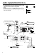
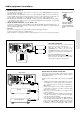
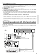
Audio equipment connections
• Do not piug in the power cord until all connections have been made.
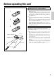
• On each pair of input jacks, a red connector (marked R) corresponds to the right
channel, and a white connector (marked L) to the left channel.
• Please refer to the instruction manual of each component when making any con-
nections.
• Insert the plugs and connectors securely. Remember that improper connection
can result in noise, poor performance, or damage to the equipment.
• Do not bind audio connection cables with power cords and speaker cables. Doing
so may degrade sound quality.
L (Left)
R (Right)
Audio connection cable
L
R
Improper Connection
Insert completely
R
V
L
R
L
R
L
R
L
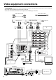
VIDEO-1
OUT
IN
VIDEO-2
VIDEO-3
OUT
IN
IN
TAPE
VIDEO
S VIDEO
OSD SELECTOR
(REC)
OUT
IN
(PLAY)
DIGITAL OUTPUT
DIGITAL INPUT
COAXIAL
1
COAXIAL
2
OPTICAL
1
OPTICAL
2
OPTICAL
FRONT
FRONT
CENTER
SUB
WOOFER
SURROUND
FRONT
CENTER
CD
PHONO
SUB
WOOFER
SURROUND
AMP IN
PRE OUT
GND
MONITOR
OUT
S
REMOTE
CONTROL
REMOTELOCAL
IN
DVD
LRLR
LR
SURROUND SPEAKERS
FRONT SPEAKERS A
CENTER
SPEAKER
FRONT SPEAKERS B
MULTI CHANNEL
INPUT
MULTI SOURCE
OUT
R
L
AV RECEIVER
DIGITAL OUTPUT
DIGITAL INPUT
COAXIAL
1
COAXIAL
2
OPTICAL
1
OPTICAL
2
OPTICAL
R
L
CD
PHONO
GND
R
L
TAPE
(REC)
OUT
IN
(PLAY)
CAUTION: SPEAKER IMPEDANCE
6 OHMS MIN. / SPEAKER
ANTENNA
AM
FM
75
AC INLET
AC OUTLETS
AC 120V 60Hz
SWITCHED
TOTAL 120W 1A MAX.
MODEL NO. DTR-7
Do not plug in the power
cord until all connections
have been made.
OUTPUT
(COAXIAL)
:Signal Flow
OUTPUT
(DIGITAL)
CD player
OUTPUT
(ANALOG)
Ground
OUTPUT
Turntable
Tape deck / MD recorder / DAT
OUTPUT
(PLAY)
INPUT
(REC)
DTR-7 / DTR-6
Audio Connection
Cable
Audio Connection Cable
Audio Connection
Cable
Optial fiber cable
Coaxial cable
Optial fiber cable
DTR-7 only
MD recorder / DAT etc...
1
2
Connect your player to COAXIAL or OP-
TICAL, whichever appropriate.
3