
10/100 Mbps LAN Physical Layer Interface Datasheet

82555 — Networking Silicon
32
Datasheet
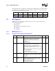
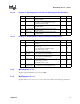
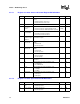
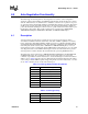
7.2.3.1 Register 16: 82555 Status and Control Register Bit Definitions
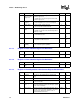
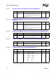
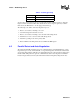
7.2.3.2 Register 17: 82555 Special Control Bit Definitions
Bit(s) Name Description Default R/W
15 Flow Control This bit enables PHY Base (Bay Technologies) flow
control.
1 = Enable PHY Base flow control
0 = Disable PHY Base flow control
0RW
14 Reserved These bits are reserved and should be set to 0b 0 RW
13 Carrier Sense
Disconnect
Control
This bit enables the disconnect function.
1 = Disconnect function enabled (default in DTE)
0 = Disconnect function disabled (default in repeater)
0 (DTE
1 (Rptr)
RW
12 Transmit Flow
Control Disable
This bit enables Transmit Flow Control
1 = Transmit Flow Control enabled
0 = Transmit Flow Control disabled
0RW
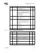
11 Receive De-
Serializer In-Sync
Indication
This bit indicates status of the 100BASE-TX Receive
De-Serializer In-Sync.
-- RO
10 100BASE-TX
Power-Down
This bit indicates the power state of 100BASE-TX
82555.
1 = Power-down
0 = Normal operation
-- RO
9 10BASE-T
Power-Down
This bit indicates the power state of 10BASE-TX
82555.
1 = Power-Down
0 = Normal operation
-- RO
8 Polarity This bit indicates 10BASE-T polarity.
1 = Reverse polarity
0 = Normal polarity
-- RO
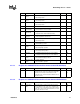
7:3 Reserved These bits are reserved and should be set to a
constant 0.
00000 RO
2 T4 This bit indicates the Auto-Negotiation result.
1 = 100BASE-T4
0 = No 100BASE-T4
-- RO
1 Speed This bit indicates the Auto-Negotiation result.
1 = 100 Mbps
0 = 10 Mbps
-- RO
0 Duplex Mode This bit indicates the Auto-Negotiation result.
1 = Full Duplex
0 = Half Duplex
-- RO
Bit(s) Name Description Default R/W
15 Scrambler By-
pass
1 = By-pass Scrambler
0 = Normal operations
0RW
14 By-pass 4B/5B 1 = 4 bit to 5 bit by-pass
0 = Normal operation
0RW