
Datasheet

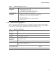
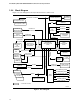
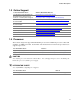


Table Of Contents
- Intel® Desktop Boards D915GEV/D915GRF Technical Product Specification
- Revision History / Disclaimer
- Preface
- Contents
- 1 Product Description
- 1.1 PCI Bus Terminology Change
- 1.2 Overview
- 1.3 Online Support
- 1.4 Processor
- 1.5 System Memory
- 1.6 Intel® 915G Chipset
- 1.7 PCI Express Connectors
- 1.8 I/O Controller
- 1.9 Audio Subsystem
- 1.10 LAN Subsystem
- 1.11 Hardware Management Subsystem
- 1.12 Power Management
- 1.12.1 ACPI
- 1.12.2 Hardware Support
- 1.12.2.1 Power Connector
- 1.12.2.2 Fan Connectors
- 1.12.2.3 LAN Wake Capabilities
- 1.12.2.4 Instantly Available PC Technology
- 1.12.2.5 Resume on Ring
- 1.12.2.6 Wake from USB
- 1.12.2.7 Wake from PS/2 Devices
- 1.12.2.8 PME# Signal Wake-up Support
- 1.12.2.9 WAKE# Signal Wake-up Support
- 1.12.2.10 +5 V Standby Power Indicator LED
- 1.13 Trusted Platform Module
- 1.13.1 System Requirements
- 1.13.2 Warning of Potential Data Loss
- 1.13.3 Security Precautions
- 1.13.4 Trusted Platform Module Ownership
- 1.13.5 Enabling the Trusted Platform Module
- 1.13.6 Assuming Trusted Platform Module Ownership
- 1.13.7 Recovery Procedures
- 1.13.8 Clearing Trusted Platform Module Ownership
- 1.13.9 Software Support
- 2 Technical Reference
- 2.1 Introduction
- 2.2 Memory Resources
- 2.3 DMA Channels
- 2.4 Fixed I/O Map
- 2.5 PCI Configuration Space Map
- 2.6 Interrupts
- 2.7 PCI Conventional Interrupt Routing Map
- 2.8 Connectors
- 2.8.1 Back Panel Connectors
- 2.8.2 Component-side Connectors
- 2.9 Jumper Block
- 2.10 Mechanical Considerations
- 2.11 Electrical Considerations
- 2.12 Thermal Considerations
- 2.13 Reliability
- 2.14 Environmental
- 2.15 Regulatory Compliance
- 3 Overview of BIOS Features
- 4 Error Messages and Beep Codes

Product Description
13
Table 1. Feature Summary (continued)
Expansion
Capabilities
•
Four PCI Conventional bus add-in card connectors (SMBus routed to PCI
Conventional bus connector 2)
•
Two PCI Express x1 bus add-in card connectors
•
One PCI Express x16 bus add-in card connector
Hardware Monitor
Subsystem
•
Hardware monitoring and fan control ASIC
•
Voltage sense to detect out of range power supply voltages
•
Thermal sense to detect out of range thermal values
•
Three fan connectors
•
Three fan sense inputs used to monitor fan activity
•
Fan speed control
1.2.2 Manufacturing Options
Table 2 describes the manufacturing options on the Desktop Boards D915GEV and D915GRF.
Not every manufacturing option is available in all marketing channels. Please contact your Intel
representative to determine which manufacturing options are available to you.
Table 2. Manufacturing Options
ATAPI CD-ROM
Connector
A connector for attaching an internal CD-ROM drive to the onboard audio subsystem
ATX Fan
Connector
Additional fan connector for use in larger chassis
IEEE-1394a
Interface
IEEE-1394a controller and three IEEE-1394a connectors (one back panel connector,
two front-panel connectors)
SCSI Hard Drive
Activity LED
Connector
Allows add-in hard drive controllers (SCSI or other) to use the same LED as the
onboard IDE controller
Serial Port B Second serial port accessible via a connector on the component side of the board
S/PDIF Connector A 1 x 3 connector (mounted on the component side of the board) that provides digital
audio signals in S/PDIF format
For information about Refer to
Available configurations for the Desktop Boards D915GEV and D915GRF Section 1.3, page 17