
Datasheet

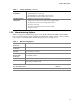
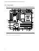
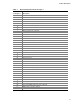
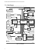


Table Of Contents
- Intel® Desktop Boards D915GEV/D915GRF Technical Product Specification
- Revision History / Disclaimer
- Preface
- Contents
- 1 Product Description
- 1.1 PCI Bus Terminology Change
- 1.2 Overview
- 1.3 Online Support
- 1.4 Processor
- 1.5 System Memory
- 1.6 Intel® 915G Chipset
- 1.7 PCI Express Connectors
- 1.8 I/O Controller
- 1.9 Audio Subsystem
- 1.10 LAN Subsystem
- 1.11 Hardware Management Subsystem
- 1.12 Power Management
- 1.12.1 ACPI
- 1.12.2 Hardware Support
- 1.12.2.1 Power Connector
- 1.12.2.2 Fan Connectors
- 1.12.2.3 LAN Wake Capabilities
- 1.12.2.4 Instantly Available PC Technology
- 1.12.2.5 Resume on Ring
- 1.12.2.6 Wake from USB
- 1.12.2.7 Wake from PS/2 Devices
- 1.12.2.8 PME# Signal Wake-up Support
- 1.12.2.9 WAKE# Signal Wake-up Support
- 1.12.2.10 +5 V Standby Power Indicator LED
- 1.13 Trusted Platform Module
- 1.13.1 System Requirements
- 1.13.2 Warning of Potential Data Loss
- 1.13.3 Security Precautions
- 1.13.4 Trusted Platform Module Ownership
- 1.13.5 Enabling the Trusted Platform Module
- 1.13.6 Assuming Trusted Platform Module Ownership
- 1.13.7 Recovery Procedures
- 1.13.8 Clearing Trusted Platform Module Ownership
- 1.13.9 Software Support
- 2 Technical Reference
- 2.1 Introduction
- 2.2 Memory Resources
- 2.3 DMA Channels
- 2.4 Fixed I/O Map
- 2.5 PCI Configuration Space Map
- 2.6 Interrupts
- 2.7 PCI Conventional Interrupt Routing Map
- 2.8 Connectors
- 2.8.1 Back Panel Connectors
- 2.8.2 Component-side Connectors
- 2.9 Jumper Block
- 2.10 Mechanical Considerations
- 2.11 Electrical Considerations
- 2.12 Thermal Considerations
- 2.13 Reliability
- 2.14 Environmental
- 2.15 Regulatory Compliance
- 3 Overview of BIOS Features
- 4 Error Messages and Beep Codes

Product Description
15
Table 3. Board Components Shown in Figure 1
Item/Callout
from Figure 1 Description
A
Rear chassis fan connector 2
B
Speaker
C
PCI Express x1 bus add-in card connectors
D
ATAPI CD-ROM connector (optional)
E
S/PDIF connector (optional)
F
Realtek ALC860 audio codec
G
Front panel audio connector
H
PCI Conventional bus add-in card connectors
I
Ethernet PLC device (optional)
J
PCI Express x16 bus add-in card connector
K
Rear chassis fan connector 1
L
Back panel connectors
M
Alternate power connector
N
+12V power connector (ATX12V)
O
LGA775 processor socket
P
Processor fan connector
Q
Intel 82915G GMCH
R
DIMM Channel A sockets
S
Serial port B connector (optional)
T
DIMM Channel B sockets
U
SCSI LED (optional)
V
I/O controller
W
Power connector
X
Diskette drive connector
Y
Parallel ATE IDE connector
Z
Battery
AA
Chassis intrusion connector
BB
BIOS Setup configuration jumper block
CC
4 Mbit Firmware Hub (FWH)
DD
Front chassis fan connector
EE
Serial ATA connectors
FF
Auxiliary front panel power LED connector
GG
Front panel connector
HH
ATX fan connector (optional)
II
Front panel USB connector
JJ
Intel 82801FB I/O Controller Hub (ICH6)
KK
Front panel IEEE-1394a connectors (optional)
LL
IEEE-1394a controller (optional)
MM
PCI Conventional bus add-in card connectors