
Datasheet

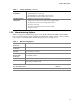
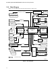
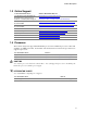


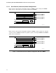
Table Of Contents
- Intel® Desktop Boards D915GEV/D915GRF Technical Product Specification
- Revision History / Disclaimer
- Preface
- Contents
- 1 Product Description
- 1.1 PCI Bus Terminology Change
- 1.2 Overview
- 1.3 Online Support
- 1.4 Processor
- 1.5 System Memory
- 1.6 Intel® 915G Chipset
- 1.7 PCI Express Connectors
- 1.8 I/O Controller
- 1.9 Audio Subsystem
- 1.10 LAN Subsystem
- 1.11 Hardware Management Subsystem
- 1.12 Power Management
- 1.12.1 ACPI
- 1.12.2 Hardware Support
- 1.12.2.1 Power Connector
- 1.12.2.2 Fan Connectors
- 1.12.2.3 LAN Wake Capabilities
- 1.12.2.4 Instantly Available PC Technology
- 1.12.2.5 Resume on Ring
- 1.12.2.6 Wake from USB
- 1.12.2.7 Wake from PS/2 Devices
- 1.12.2.8 PME# Signal Wake-up Support
- 1.12.2.9 WAKE# Signal Wake-up Support
- 1.12.2.10 +5 V Standby Power Indicator LED
- 1.13 Trusted Platform Module
- 1.13.1 System Requirements
- 1.13.2 Warning of Potential Data Loss
- 1.13.3 Security Precautions
- 1.13.4 Trusted Platform Module Ownership
- 1.13.5 Enabling the Trusted Platform Module
- 1.13.6 Assuming Trusted Platform Module Ownership
- 1.13.7 Recovery Procedures
- 1.13.8 Clearing Trusted Platform Module Ownership
- 1.13.9 Software Support
- 2 Technical Reference
- 2.1 Introduction
- 2.2 Memory Resources
- 2.3 DMA Channels
- 2.4 Fixed I/O Map
- 2.5 PCI Configuration Space Map
- 2.6 Interrupts
- 2.7 PCI Conventional Interrupt Routing Map
- 2.8 Connectors
- 2.8.1 Back Panel Connectors
- 2.8.2 Component-side Connectors
- 2.9 Jumper Block
- 2.10 Mechanical Considerations
- 2.11 Electrical Considerations
- 2.12 Thermal Considerations
- 2.13 Reliability
- 2.14 Environmental
- 2.15 Regulatory Compliance
- 3 Overview of BIOS Features
- 4 Error Messages and Beep Codes

Intel Desktop Board D915GEV/D915GRF Technical Product Specification
18
1.5 System Memory
The boards have four DIMM sockets and support the following memory features:
•
1.8 V (only) DDR2 SDRAM DIMMs with gold-plated contacts
•
Unbuffered, single-sided or double-sided DIMMs with the following restriction:
Double-sided DIMMS with x16 organization are not supported.
•
4 GB maximum total system memory. Refer to Section 2.2.1 on page 51 for information on
the total amount of addressable memory.
•
Minimum total system memory: 128 MB
•
Non-ECC DIMMs
•
Serial Presence Detect
•
DDR2 533 MHz or DDR2 400 MHz SDRAM DIMMs
NOTES
•
Remove the PCI Express x16 video card before installing or upgrading memory to avoid
interference with the memory retention mechanism.
• To be fully compliant with all applicable DDR SDRAM memory specifications, the board
should be populated with DIMMs that support the Serial Presence Detect (SPD) data
structure. This allows the BIOS to read the SPD data and program the chipset to accurately
configure memory settings for optimum performance. If non-SPD memory is installed, the
BIOS will attempt to correctly configure the memory settings, but performance and reliability
may be impacted or the DIMMs may not function under the determined frequency.
Table 4 lists the supported DIMM configurations.
Table 4. Supported Memory Configurations
DIMM
Capacity Configuration
SDRAM
Density
SDRAM Organization
Front-side/Back-side
Number of SDRAM
Devices
128 MB SS 256 Mbit 16 M x 16/empty 4
256 MB SS 256 Mbit 32 M x 8/empty 8
256 MB SS 512 Mbit 32 M x 16/empty 4
512 MB DS 256 Mbit 32 M x 8/32 M x 8 16
512 MB SS 512 Mbit 64 M x 8/empty 8
512 MB SS 1 Gbit 64 M x 16/empty 4
1024 MB DS 512 Mbit 64 M x 8/64 M x 8 16
1024 MB SS 1 Gbit 128 M x 8/empty 8
2048 MB DS 1 Gbit 128 M x 8/128 M x 8 16
Note: In the second column, “DS” refers to double-sided memory modules (containing two rows of SDRAM) and “SS”
refers to single-sided memory modules (containing one row of SDRAM).
INTEGRATOR’S NOTE
It is possible to install four 2048 MB (2 GB) modules for a total of 8 GB of system memory,
however, only 4 GB of address space is available. Refer to Section 2.2.1, on page 51 for
additional information on available memory.