
Datasheet


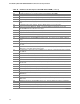
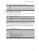

Table Of Contents
- Intel® Desktop Boards D915GEV/D915GRF Technical Product Specification
- Revision History / Disclaimer
- Preface
- Contents
- 1 Product Description
- 1.1 PCI Bus Terminology Change
- 1.2 Overview
- 1.3 Online Support
- 1.4 Processor
- 1.5 System Memory
- 1.6 Intel® 915G Chipset
- 1.7 PCI Express Connectors
- 1.8 I/O Controller
- 1.9 Audio Subsystem
- 1.10 LAN Subsystem
- 1.11 Hardware Management Subsystem
- 1.12 Power Management
- 1.12.1 ACPI
- 1.12.2 Hardware Support
- 1.12.2.1 Power Connector
- 1.12.2.2 Fan Connectors
- 1.12.2.3 LAN Wake Capabilities
- 1.12.2.4 Instantly Available PC Technology
- 1.12.2.5 Resume on Ring
- 1.12.2.6 Wake from USB
- 1.12.2.7 Wake from PS/2 Devices
- 1.12.2.8 PME# Signal Wake-up Support
- 1.12.2.9 WAKE# Signal Wake-up Support
- 1.12.2.10 +5 V Standby Power Indicator LED
- 1.13 Trusted Platform Module
- 1.13.1 System Requirements
- 1.13.2 Warning of Potential Data Loss
- 1.13.3 Security Precautions
- 1.13.4 Trusted Platform Module Ownership
- 1.13.5 Enabling the Trusted Platform Module
- 1.13.6 Assuming Trusted Platform Module Ownership
- 1.13.7 Recovery Procedures
- 1.13.8 Clearing Trusted Platform Module Ownership
- 1.13.9 Software Support
- 2 Technical Reference
- 2.1 Introduction
- 2.2 Memory Resources
- 2.3 DMA Channels
- 2.4 Fixed I/O Map
- 2.5 PCI Configuration Space Map
- 2.6 Interrupts
- 2.7 PCI Conventional Interrupt Routing Map
- 2.8 Connectors
- 2.8.1 Back Panel Connectors
- 2.8.2 Component-side Connectors
- 2.9 Jumper Block
- 2.10 Mechanical Considerations
- 2.11 Electrical Considerations
- 2.12 Thermal Considerations
- 2.13 Reliability
- 2.14 Environmental
- 2.15 Regulatory Compliance
- 3 Overview of BIOS Features
- 4 Error Messages and Beep Codes

Overview of BIOS Features
91
3.9 BIOS Security Features
The BIOS includes security features that restrict access to the BIOS Setup program and who can
boot the computer. A supervisor password and a user password can be set for the BIOS Setup
program and for booting the computer, with the following restrictions:
•
The supervisor password gives unrestricted access to view and change all the Setup options in
the BIOS Setup program. This is the supervisor mode.
•
The user password gives restricted access to view and change Setup options in the BIOS Setup
program. This is the user mode.
•
If only the supervisor password is set, pressing the <Enter> key at the password prompt of the
BIOS Setup program allows the user restricted access to Setup.
•
If both the supervisor and user passwords are set, users can enter either the supervisor
password or the user password to access Setup. Users have access to Setup respective to
which password is entered.
•
Setting the user password restricts who can boot the computer. The password prompt will be
displayed before the computer is booted. If only the supervisor password is set, the computer
boots without asking for a password. If both passwords are set, the user can enter either
password to boot the computer.
• For enhanced security, use different passwords for the supervisor and user passwords.
• Valid password characters are A-Z, a-z, and 0-9. Passwords may be up to 16 characters in
length.
Table 45 shows the effects of setting the supervisor password and user password. This table is for
reference only and is not displayed on the screen.
Table 45. Supervisor and User Password Functions
Password Set
Supervisor
Mode
User Mode
Setup Options
Password to
Enter Setup
Password
During Boot
Neither Can change all
options
(Note)
Can change all
options
(Note)
None None None
Supervisor
only
Can change all
options
Can change a
limited number
of options
Supervisor Password Supervisor None
User only N/A Can change all
options
Enter Password
Clear User Password
User User
Supervisor
and user set
Can change all
options
Can change a
limited number
of options
Supervisor Password
Enter Password
Supervisor or
user
Supervisor or
user
Note: If no password is set, any user can change all Setup options.