
Datasheet


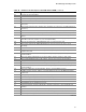
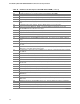
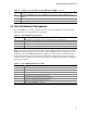

Table Of Contents
- Intel® Desktop Boards D915GEV/D915GRF Technical Product Specification
- Revision History / Disclaimer
- Preface
- Contents
- 1 Product Description
- 1.1 PCI Bus Terminology Change
- 1.2 Overview
- 1.3 Online Support
- 1.4 Processor
- 1.5 System Memory
- 1.6 Intel® 915G Chipset
- 1.7 PCI Express Connectors
- 1.8 I/O Controller
- 1.9 Audio Subsystem
- 1.10 LAN Subsystem
- 1.11 Hardware Management Subsystem
- 1.12 Power Management
- 1.12.1 ACPI
- 1.12.2 Hardware Support
- 1.12.2.1 Power Connector
- 1.12.2.2 Fan Connectors
- 1.12.2.3 LAN Wake Capabilities
- 1.12.2.4 Instantly Available PC Technology
- 1.12.2.5 Resume on Ring
- 1.12.2.6 Wake from USB
- 1.12.2.7 Wake from PS/2 Devices
- 1.12.2.8 PME# Signal Wake-up Support
- 1.12.2.9 WAKE# Signal Wake-up Support
- 1.12.2.10 +5 V Standby Power Indicator LED
- 1.13 Trusted Platform Module
- 1.13.1 System Requirements
- 1.13.2 Warning of Potential Data Loss
- 1.13.3 Security Precautions
- 1.13.4 Trusted Platform Module Ownership
- 1.13.5 Enabling the Trusted Platform Module
- 1.13.6 Assuming Trusted Platform Module Ownership
- 1.13.7 Recovery Procedures
- 1.13.8 Clearing Trusted Platform Module Ownership
- 1.13.9 Software Support
- 2 Technical Reference
- 2.1 Introduction
- 2.2 Memory Resources
- 2.3 DMA Channels
- 2.4 Fixed I/O Map
- 2.5 PCI Configuration Space Map
- 2.6 Interrupts
- 2.7 PCI Conventional Interrupt Routing Map
- 2.8 Connectors
- 2.8.1 Back Panel Connectors
- 2.8.2 Component-side Connectors
- 2.9 Jumper Block
- 2.10 Mechanical Considerations
- 2.11 Electrical Considerations
- 2.12 Thermal Considerations
- 2.13 Reliability
- 2.14 Environmental
- 2.15 Regulatory Compliance
- 3 Overview of BIOS Features
- 4 Error Messages and Beep Codes

93
4 Error Messages and Beep Codes
What This Chapter Contains
4.1
BIOS Error Messages ................................................................................................93
4.2
Port 80h POST Codes................................................................................................95
4.3 Bus Initialization Checkpoints .....................................................................................99
4.4 Speaker....................................................................................................................100
4.5
BIOS Beep Codes ....................................................................................................100
4.1 BIOS Error Messages
Table 46 lists the error messages and provides a brief description of each.
Table 46. BIOS Error Messages
Error Message Explanation
GA20 Error An error occurred with Gate A20 when switching to protected
mode during the memory test.
Pri Master HDD Error
Pri Slave HDD Error
Could not read sector from corresponding drive.
Pri Master Drive - ATAPI Incompatible
Pri Slave Drive - ATAPI Incompatible
Corresponding drive in not an ATAPI device. Run Setup to make
sure device is selected correctly.
A: Drive Error No response from diskette drive.
Cache Memory Bad An error occurred when testing L2 cache. Cache memory may be
bad.
CMOS Battery Low The battery may be losing power. Replace the battery soon.
CMOS Display Type Wrong The display type is different than what has been stored in CMOS.
Check Setup to make sure type is correct.
CMOS Checksum Bad The CMOS checksum is incorrect. CMOS memory may have
been corrupted. Run Setup to reset values.
CMOS Settings Wrong CMOS values are not the same as the last boot. These values
have either been corrupted or the battery has failed.
CMOS Date/Time Not Set The time and/or date values stored in CMOS are invalid. Run
Setup to set correct values.
DMA Error Error during read/write test of DMA controller.
FDC Failure Error occurred trying to access diskette drive controller.
HDC Failure Error occurred trying to access hard disk controller.
Checking NVRAM..... NVRAM is being checked to see if it is valid.
continued