
Datasheet


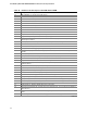
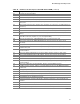
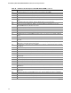
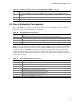

Table Of Contents
- Intel® Desktop Boards D915GEV/D915GRF Technical Product Specification
- Revision History / Disclaimer
- Preface
- Contents
- 1 Product Description
- 1.1 PCI Bus Terminology Change
- 1.2 Overview
- 1.3 Online Support
- 1.4 Processor
- 1.5 System Memory
- 1.6 Intel® 915G Chipset
- 1.7 PCI Express Connectors
- 1.8 I/O Controller
- 1.9 Audio Subsystem
- 1.10 LAN Subsystem
- 1.11 Hardware Management Subsystem
- 1.12 Power Management
- 1.12.1 ACPI
- 1.12.2 Hardware Support
- 1.12.2.1 Power Connector
- 1.12.2.2 Fan Connectors
- 1.12.2.3 LAN Wake Capabilities
- 1.12.2.4 Instantly Available PC Technology
- 1.12.2.5 Resume on Ring
- 1.12.2.6 Wake from USB
- 1.12.2.7 Wake from PS/2 Devices
- 1.12.2.8 PME# Signal Wake-up Support
- 1.12.2.9 WAKE# Signal Wake-up Support
- 1.12.2.10 +5 V Standby Power Indicator LED
- 1.13 Trusted Platform Module
- 1.13.1 System Requirements
- 1.13.2 Warning of Potential Data Loss
- 1.13.3 Security Precautions
- 1.13.4 Trusted Platform Module Ownership
- 1.13.5 Enabling the Trusted Platform Module
- 1.13.6 Assuming Trusted Platform Module Ownership
- 1.13.7 Recovery Procedures
- 1.13.8 Clearing Trusted Platform Module Ownership
- 1.13.9 Software Support
- 2 Technical Reference
- 2.1 Introduction
- 2.2 Memory Resources
- 2.3 DMA Channels
- 2.4 Fixed I/O Map
- 2.5 PCI Configuration Space Map
- 2.6 Interrupts
- 2.7 PCI Conventional Interrupt Routing Map
- 2.8 Connectors
- 2.8.1 Back Panel Connectors
- 2.8.2 Component-side Connectors
- 2.9 Jumper Block
- 2.10 Mechanical Considerations
- 2.11 Electrical Considerations
- 2.12 Thermal Considerations
- 2.13 Reliability
- 2.14 Environmental
- 2.15 Regulatory Compliance
- 3 Overview of BIOS Features
- 4 Error Messages and Beep Codes

Error Messages and Beep Codes
97
Table 49. Runtime Code Uncompressed in F000 Shadow RAM (continued)
Code Description of POST Operation
40 To prepare the descriptor tables.
42 To enter in virtual mode for memory test.
43 To enable interrupts for diagnostics mode.
44 To initialize data to check memory wrap around at 0:0.
45 Data initialized. Going to check for memory wrap around at 0:0 and finding the total system
memory size.
46 Memory wrap around test done. Memory size calculation over. About to go for writing patterns to
test memory.
47 Pattern to be tested written in extended memory. Going to write patterns in base 640k memory.
48 Patterns written in base memory. Going to find out amount of memory below 1M memory.
49 Amount of memory below 1M found and verified. Going to find out amount of memory above 1M
memory.
4B Amount of memory above 1M found and verified. Check for soft reset and going to clear memory
below 1M for soft reset. (If power on, go to check point # 4Eh).
4C Memory below 1M cleared. (SOFT RESET) Going to clear memory above 1M.
4D Memory above 1M cleared. (SOFT RESET) Going to save the memory size. (Go to check
point # 52h).
4E Memory test started. (NOT SOFT RESET) About to display the first 64k memory size.
4F Memory size display started. This will be updated during memory test. Going for sequential and
random memory test.
50 Memory testing/initialization below 1M complete. Going to adjust displayed memory size for
relocation/shadow.
51 Memory size display adjusted due to relocation/ shadow. Memory test above 1M to follow.
52 Memory testing/initialization above 1M complete. Going to save memory size information.
53 Memory size information is saved. CPU registers are saved. Going to enter in real mode.
54 Shutdown successful, CPU in real mode. Going to disable gate A20 line and disable parity/NMI.
57 A20 address line, parity/NMI disable successful. Going to adjust memory size depending on
relocation/shadow.
58 Memory size adjusted for relocation/shadow. Going to clear Hit <DEL> message.
59 Hit <DEL> message cleared. <WAIT...> message displayed. About to start DMA and interrupt
controller test.
60 DMA page register test passed. To do DMA#1 base register test.
62 DMA#1 base register test passed. To do DMA#2 base register test.
65 DMA#2 base register test passed. To program DMA unit 1 and 2.
66 DMA unit 1 and 2 programming over. To initialize 8259 interrupt controller.
7F Extended NMI sources enabling is in progress.
80 Keyboard test started. Clearing output buffer, checking for stuck key, to issue keyboard reset
command.
81 Keyboard reset error/stuck key found. To issue keyboard controller interface test command.
82 Keyboard controller interface test over. To write command byte and init circular buffer.
83 Command byte written, global data init done. To check for lock-key.
continued