
Datasheet


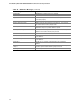

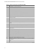
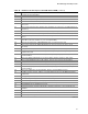
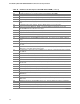
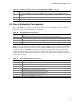

Table Of Contents
- Intel® Desktop Boards D915GEV/D915GRF Technical Product Specification
- Revision History / Disclaimer
- Preface
- Contents
- 1 Product Description
- 1.1 PCI Bus Terminology Change
- 1.2 Overview
- 1.3 Online Support
- 1.4 Processor
- 1.5 System Memory
- 1.6 Intel® 915G Chipset
- 1.7 PCI Express Connectors
- 1.8 I/O Controller
- 1.9 Audio Subsystem
- 1.10 LAN Subsystem
- 1.11 Hardware Management Subsystem
- 1.12 Power Management
- 1.12.1 ACPI
- 1.12.2 Hardware Support
- 1.12.2.1 Power Connector
- 1.12.2.2 Fan Connectors
- 1.12.2.3 LAN Wake Capabilities
- 1.12.2.4 Instantly Available PC Technology
- 1.12.2.5 Resume on Ring
- 1.12.2.6 Wake from USB
- 1.12.2.7 Wake from PS/2 Devices
- 1.12.2.8 PME# Signal Wake-up Support
- 1.12.2.9 WAKE# Signal Wake-up Support
- 1.12.2.10 +5 V Standby Power Indicator LED
- 1.13 Trusted Platform Module
- 1.13.1 System Requirements
- 1.13.2 Warning of Potential Data Loss
- 1.13.3 Security Precautions
- 1.13.4 Trusted Platform Module Ownership
- 1.13.5 Enabling the Trusted Platform Module
- 1.13.6 Assuming Trusted Platform Module Ownership
- 1.13.7 Recovery Procedures
- 1.13.8 Clearing Trusted Platform Module Ownership
- 1.13.9 Software Support
- 2 Technical Reference
- 2.1 Introduction
- 2.2 Memory Resources
- 2.3 DMA Channels
- 2.4 Fixed I/O Map
- 2.5 PCI Configuration Space Map
- 2.6 Interrupts
- 2.7 PCI Conventional Interrupt Routing Map
- 2.8 Connectors
- 2.8.1 Back Panel Connectors
- 2.8.2 Component-side Connectors
- 2.9 Jumper Block
- 2.10 Mechanical Considerations
- 2.11 Electrical Considerations
- 2.12 Thermal Considerations
- 2.13 Reliability
- 2.14 Environmental
- 2.15 Regulatory Compliance
- 3 Overview of BIOS Features
- 4 Error Messages and Beep Codes

Intel Desktop Board D915GEV/D915GRF Technical Product Specification
98
Table 49. Runtime Code Uncompressed in F000 Shadow RAM (continued)
Code Description of POST Operation
84 Lock-key checking over. To check for memory size mismatch with CMOS.
85 Memory size check done. To display soft error and check for password or bypass setup.
86 Password checked. About to do programming before setup.
87 Programming before setup complete. To uncompress SETUP code and execute CMOS setup.
88 Returned from CMOS setup program and screen is cleared. About to do programming after
setup.
89 Programming after setup complete. Going to display power-on screen message.
8B First screen message displayed. <WAIT...> message displayed. PS/2 Mouse check and
extended BIOS data area allocation to be done.
8C Setup options programming after CMOS setup about to start.
8D Going for hard disk controller reset.
8F Hard disk controller reset done. Floppy setup to be done next.
91 Floppy setup complete. Hard disk setup to be done next.
95 Init of different buses optional ROMs from C800 to start. (See Section 4.3 for details of different
buses.)
96 Going to do any init before C800 optional ROM control.
97 Any init before C800 optional ROM control is over. Optional ROM check and control will be
done next.
98 Optional ROM control is done. About to give control to do any required processing after optional
ROM returns control and enable external cache.
99 Any initialization required after optional ROM test over. Going to setup timer data area and printer
base address.
9A Return after setting timer and printer base address. Going to set the RS-232 base address.
9B Returned after RS-232 base address. Going to do any initialization before Coprocessor test.
9C Required initialization before Coprocessor is over. Going to initialize the Coprocessor next.
9D Coprocessor initialized. Going to do any initialization after Coprocessor test.
9E Initialization after Coprocessor test is complete. Going to check extended keyboard, keyboard ID
and num-lock.
A2 Going to display any soft errors.
A3 Soft error display complete. Going to set keyboard typematic rate.
A4 Keyboard typematic rate set. To program memory wait states.
A5 Going to enable parity/NMI.
A7 NMI and parity enabled. Going to do any initialization required before giving control to optional
ROM at E000.
A8 Initialization before E000 ROM control over. E000 ROM to get control next.
A9 Returned from E000 ROM control. Going to do any initialization required after E000 optional
ROM control.
AA Initialization after E000 optional ROM control is over. Going to display the system configuration.
AB Put INT13 module runtime image to shadow.
AC Generate MP for multiprocessor support (if present).
AD Put CGA INT10 module (if present) in Shadow.
continued