
Datasheet


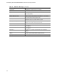

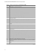
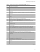

Table Of Contents
- Intel® Desktop Boards D915GEV/D915GRF Technical Product Specification
- Revision History / Disclaimer
- Preface
- Contents
- 1 Product Description
- 1.1 PCI Bus Terminology Change
- 1.2 Overview
- 1.3 Online Support
- 1.4 Processor
- 1.5 System Memory
- 1.6 Intel® 915G Chipset
- 1.7 PCI Express Connectors
- 1.8 I/O Controller
- 1.9 Audio Subsystem
- 1.10 LAN Subsystem
- 1.11 Hardware Management Subsystem
- 1.12 Power Management
- 1.12.1 ACPI
- 1.12.2 Hardware Support
- 1.12.2.1 Power Connector
- 1.12.2.2 Fan Connectors
- 1.12.2.3 LAN Wake Capabilities
- 1.12.2.4 Instantly Available PC Technology
- 1.12.2.5 Resume on Ring
- 1.12.2.6 Wake from USB
- 1.12.2.7 Wake from PS/2 Devices
- 1.12.2.8 PME# Signal Wake-up Support
- 1.12.2.9 WAKE# Signal Wake-up Support
- 1.12.2.10 +5 V Standby Power Indicator LED
- 1.13 Trusted Platform Module
- 1.13.1 System Requirements
- 1.13.2 Warning of Potential Data Loss
- 1.13.3 Security Precautions
- 1.13.4 Trusted Platform Module Ownership
- 1.13.5 Enabling the Trusted Platform Module
- 1.13.6 Assuming Trusted Platform Module Ownership
- 1.13.7 Recovery Procedures
- 1.13.8 Clearing Trusted Platform Module Ownership
- 1.13.9 Software Support
- 2 Technical Reference
- 2.1 Introduction
- 2.2 Memory Resources
- 2.3 DMA Channels
- 2.4 Fixed I/O Map
- 2.5 PCI Configuration Space Map
- 2.6 Interrupts
- 2.7 PCI Conventional Interrupt Routing Map
- 2.8 Connectors
- 2.8.1 Back Panel Connectors
- 2.8.2 Component-side Connectors
- 2.9 Jumper Block
- 2.10 Mechanical Considerations
- 2.11 Electrical Considerations
- 2.12 Thermal Considerations
- 2.13 Reliability
- 2.14 Environmental
- 2.15 Regulatory Compliance
- 3 Overview of BIOS Features
- 4 Error Messages and Beep Codes

Error Messages and Beep Codes
99
Table 49. Runtime Code Uncompressed in F000 Shadow RAM (continued)
Code Description of POST Operation
AE Uncompress SMBIOS module and init SMBIOS code and form the runtime SMBIOS image in
shadow.
B1 Going to copy any code to specific area.
00 Copying of code to specific area done. Going to give control to INT-19 boot loader.
4.3 Bus Initialization Checkpoints
The system BIOS gives control to the different buses at several checkpoints to do various tasks.
Table 50 describes the bus initialization checkpoints.
Table 50. Bus Initialization Checkpoints
Checkpoint Description
2A Different buses init (system, static, and output devices) to start if present.
38 Different buses init (input, IPL, and general devices) to start if present.
39 Display different buses initialization error messages.
95 Init of different buses optional ROMs from C800 to start.
While control is inside the different bus routines, additional checkpoints are output to port 80h as
WORD to identify the routines under execution. In these WORD checkpoints, the low byte of the
checkpoint is the system BIOS checkpoint from which the control is passed to the different bus
routines. The high byte of the checkpoint is the indication of which routine is being executed in
the different buses. Table 51 describes the upper nibble of the high byte and indicates the function
that is being executed.
Table 51. Upper Nibble High Byte Functions
Value Description
0 func#0, disable all devices on the bus concerned.
1 func#1, static devices init on the bus concerned.
2 func#2, output device init on the bus concerned.
3 func#3, input device init on the bus concerned.
4 func#4, IPL device init on the bus concerned.
5 func#5, general device init on the bus concerned.
6 func#6, error reporting for the bus concerned.
7 func#7, add-on ROM init for all buses.