
Network Card User Manual


MPCMM0001 Chassis Management Module Software Technical Product Specification 69
Power and Hot Swap Management
7.4 Surprise FRU Extraction/IPMI Failure
The CMM detects a surprise FRU extraction or a failure of the IPMI device fronting the FRU if a
device previously in one of the M2-7 states reports a transition to the M2 state. If this scenario is
detected, the CMM assumes one of three things has happened:
• Surprise extraction and reinsertion of the same (or another) FRU.
• IPMI Device fronting the FRU failed, FRU was extracted, then the same (or another) FRU is
reinserted.
• Watchdog Timer (WDT) on the IPMI device restarted the IPMI Device firmware.
Once this occurs, the CMM shall reclaim all the resources allocated to that FRU. The CMM will
log a SEL message describing the situation, i.e. IPMI device failure or surprise extraction. From
this point the CMM shall follow the sequence of actions described in Section 7.2, “FRU Insertion”.
7.5 Forced Power State Changes
An external authorized entity (e.g., a management interface like RMCP) can request FRU power
state changes like Power OFF, RESET etc. The CMM is responsible for handling these requests.
7.6 Power Management on the Standby CMM
The standby CMM does not participate in any power management activities in the standby mode.
The CMM is in a hot standby state on a standby CMM. The standby CMM starts performing power
management activities as soon as it becomes the active CMM.
7.7 Power Feed Targets
The CLI allows certain get and set actions to be taken on power feeds for a location. They include
the following dataitems; maxexternalavailablecurrent, maxinternalcurrent, and
minexpectedoperatingvoltage. These dataitems are described in Section 8, “The Command Line
Interface (CLI)” on page 71.
To find the number of feed targets, use the command:
cmmget -l cmm -d feedcount
This returns an integer, indicating the number of power feeds.
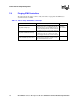
As an example, the MPCHC0001 chassis with four power feeds coming from the PEMs will return
the number 4, meaning there are four feed targets (feed1, feed2, feed3, and feed4). They correlate
to the physical feeds on the MPCHC0001as follows:
feed1 = FeedA1
feed2 = FeedB2
feed3 = FeedA2
feed4 = FeedB1
Refer to the chassis documentation for more information on power feeds.