Concord Express Installation Instructions P/N 466-1665 • REV J • OCT12
Copyright Trademarks and patents Manufacturer Contact information Customer support © 2012 UTC Fire & Security Americas Corporation, Inc. Interlogix is part of UTC Climate Controls & Security, a unit of United Technologies Corporation. All rights reserved. Concord is trademarks of UTC Fire & Security. Other trade names used in this document may be trademarks or registered trademarks of the manufacturers or vendors of the respective products. UTC Fire & Security Americas Corporation, Inc. 1275 Red Fox Rd.
A plug and jack used to connect this equipment to the premises wiring and telephone network must comply with the applicable FCC Part 68 rules and requirements as adopted by ACTA. A compliant telephone cord and modular plug is provided with this product. It is designed to be connected to a compliant modular jack that is also compliant. See the Installation Instructions for details. Alarm dialing equipment must be able to seize the telephone line and place a call in an emergency situation.
Before installing this equipment, users should ensure that it is permissible to be connected to the facilities of the local telecommunications company. The equipment must also be installed using an acceptable method of connection. In some cases, the company’s inside wiring associated with a single-line individual service may be extended by means of a certified connector assembly (telephone extension cord).
Content Notices Chapter 1 Installation 1 Special installation requirements Planning the Installation 6 Installing the System 7 2 Chapter 2 Programming 27 Entering programming mode 28 Programming Tier 1 Menu Items 30 Programming Tier 2 Menu Items 32 Chapter 3 Testing/Troubleshooting 71 Troubleshooting 76 Appendix A System configuration worksheets 85 Appendix B Programming mode menus and settings 103 Appendix C Software release notes and specifications 107 Concord Express Installation Instructions i
Chapter 1 Installation This manual provides information for planning, installing, programming, and testing this security system. When necessary, this manual refers you to other documentation included with compatible devices. Planning sheets are included for you to record hardware layout and software programming settings.
Chapter 1 Special installation requirements This security system can be used as a wire warning system, an intrusion alarm system, an emergency notification system, or any combination of the three. Some installations may require configurations dictated by city or state codes, insurance, or Underwriter’s Laboratories (UL). This section describes the various component and configuration listings. UL Listed Systems This section describes the requirements for UL Listed systems.
Chapter 1 • RF TX TIMEOUT set to 24 hours • EXTENDED DELAY set to off • TWO TRIP ERROR set to off • ALARM VERIFY set to off • DISABLE TROUBLE BEEPS set to off • SYSTEM TAMPER set to on Household Fire Warning System (UL 985) Basic system plus: • Hardwire Smoke Detector: System Sensor models 2100D, 2100TD, 2100S, 2100TS, 2400, or 2400TH learned into Sensor Group 26 Sentrol (ESL) models 429AT, 521B, or 521BXT learned into sensor group 26 • Wireless Smoke Sensor 60-506-319.
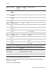
Chapter 1 Shortcut Function # Programmin g page reference Default setting Required setting 0003 SIA False Alarm Reduction 34 On On 0013 Exit Extension 35 On On 0014 Auto Stay Arming 35 On On 0016 Duress Code 36 Disabled Disabled 02005 Dialer Abort 43 On On 02006 Dialer Abort Delay 43 30 Sec. 15-45 sec. 02007 Cancel Message 43 On On 02009 Call Wait Cancel 44 Disabled On if reporting to central station and customer has call waiting 0310 Entry Delay 46 30 sec.
Chapter 1 • • • • • • • • • • • AC FAILURE set to on PHONE NUMBER must be programmed HIGH LEVEL REPORTS set to on. LOW LEVEL REPORTS set to on PHONE TEST set to on AUTO PHONE TEST set to on PHONE TEST FREQ.
Chapter 1 • SMOKE VERIFY must be set to off Planning the Installation This section describes the system capabilities to help you get familiar with the system. To help you prepare for system installation, Appendix A provides planning sheets with tables that let you record the hardware and programming configuration of the system. Standard Panel The following describes the basic panel (out-of-box) hardware capabilities. • Power: Input for an AC step-down, plug-in style transformer.
Chapter 1 • SuperBus 2000 2x20 LCD/VFD Alphanumeric Touchpads: Provide complete system programming and operation control, display system messages and indicate system status. • SuperBus 2000 Fixed Display LCD Touchpad: Provides operation control and user programming access (not installer or dealer programming). Displays system messages and indicates system status.
Chapter 1 Determine the Panel Location Before permanently mounting the panel, determine the location using the following guidelines: • To help reduce wire run lengths and labor, centrally locate the panel with relation to detection devices whenever possible. • Avoid running wires parallel with electrical wiring or fixtures, such as fluorescent lighting, to prevent wire runs from picking up electrical noise.
Chapter 1 (B) Class 2, Class 3, and power-limited fire alarm circuit conductors must be installed as Class 1 or higher circuits. Table 1 below describes panel voltage/current output ranges. See Appendix A for maximum and standby device current draw. Table 1: Panel voltage/surrent output ranges Panel terminal Voltage range Max. current 4 (+12V) 8.5 - 14.2 VDC 9.1 - 14.2 VDC (UL) 750 mA—non-UL Listed systems 90 mA—UL Listed systems 7 (OUT1/+12) 8.5 - 14.2 VDC 1.
Chapter 1 Device Max. wire length to panel Wire type SuperBus 2000 2x20 VFD Alphanumeric Touchpad 22 AWG—250 ft. 18 AWG— 600 ft. Stranded SuperBus 2000 Hardwire Input Module 22 AWG—1,800 ft. 18 AWG— 4,500 ft. Stranded Mounting the Panel Use the following procedure to mount the panel to the wall or wall studs. Caution: Make sure you are free of static electricity whenever you work on the panel with the cover open.
Chapter 1 5. Install anchors where studs are not present. 6. Partially insert screws into the two top mounting hole locations, then hang the panel on the two screws. 7. Recheck for levelness, insert the two lower screws, and tighten all four mounting screws. 8. Install the antenna housing (included with the panel) by pushing it down into the top left hole of the cabinet until it snaps into place (see Figure 3 below). 9.
Chapter 1 Figure 4: Main component locations Connecting the Panel to Earth Ground For maximum protection from lightning strikes and transients, connect the lowerright circuit board screw to earth ground as shown in Figure 5 below. Use 16gauge, solid copper wire from an earth grounded cold water pipe clamp to the panel. Note: For best results, it is recommended that you crimp a spade lug on the wire end at the panel and secure the lug under the circuit board screw as shown in Figure 5 below.
Chapter 1 Installing Optional SnapCards The SnapCard Header on the lower-left side of the panel accepts one of the following SnapCard models: • • • 8Z Input SnapCard—60-757 4 Output SnapCard—60-758 4Z Input/2 Output Combo SnapCard—60-756 Install the desired SnapCard onto the panel SnapCard Header and secure it in place with two screws, included with the card (Figure 6 below). Connect all necessary input/output wiring using the installation instructions included with the SnapCard.
Chapter 1 Figure 7: Installing and connecting the HIM in the Concord Express Connecting Detection Devices to Panel Zone Inputs The panel comes with six factory programmed onboard hardwire zones (see “Accessory Modules Menu” on page 60 for factory settings). Zone inputs 1 through 6 are supervised using a 2k-ohm, end-of-line resistor (included with panel) at the last device on the circuit. Note: Install an end-of-line resistor on all unused, factory programmed, onboard panel zones.
Chapter 1 Figure 8: Connecting N/C and N/O intrusion detection circuits Figure 9 below shows the typical wiring for Optex model RX-040 (PI) PIR motion detectors. The minimum available panel voltage for hardwired PIR motion detectors is 8.5 VDC (9.1 VDC for UL Listed systems).
Chapter 1 Note: When using 2-wire smoke detectors on Zone 6, the Two-Wire Smoke setting (in program mode) must be turned on before entering the LEARN SENSORS menu. See ONBOARD OPTIONS—INPUTS in the section “Entering programming mode” on page 28 for complete details. WARNING: Use only 2-wire smoke detector models described above. Alarm signals from other detectors may not be processed correctly if the panel has lost AC power and is operating only from the backup battery.
Chapter 1 The panel provides this power interruption from panel terminal 8 (OUT2/OC) provided that the output configuration number is set (in program mode) to 01500. For more information on output configuration numbers, see the section “Programming the Panel” and the tables in Appendix A. Use only 4-wire smoke detectors that operate on 8.5 to 14.2 VDC. Note: The Two-Wire Smoke setting (in program mode) must be off when connecting 4-wire smoke detectors to zone 6.
Chapter 1 Note: If the backup battery is not connected, or if the configuration of panel terminal 7 is programmed to anything other than the default (00410), then the combined currents of terminal 7 (OUT 1/+12) and terminal 4 (+12V) must not exceed 750 mA. 15-Watt, Dual Tone Siren (13-469) Panel terminal 7 (OUT1/+12V) is a +12V programmable output. At the default configuration setting (00410), this output can provide up to 1.
Chapter 1 Figure 13: Connecting hardwire siren 13-046 Interior Piezo Siren (30-006) Panel terminal 8 (OUT2/OC) is an open-collector (switched path-to-ground), programmable output that can handle up to a 200 mA current. The default setting (01710) activates the output for status and alarm tones, which allows for a piezo siren connection without changing the output configuration number. Connect the piezo siren to the panel terminals with a 2k end-of-line resistor as shown in Figure 14 below.
Chapter 1 Panel terminal 7 (OUT1/+12V) is a +12-volt programmable output. At the default configuration setting (00410), this output can provide up to 1.25 A during an alarm (650 mA for UL Listed systems) if the backup battery is connected. Note: If the backup battery is not connected, or if the configuration of panel terminal 7 is programmed to anything other than the default (00410), then the combined currents of terminal 7 (OUT 1/+12) and terminal 4 (+12V) must not exceed 750 mA.
Chapter 1 Connect 2x20 LCD/VFD touchpads to the panel power output and bus terminals as shown in Figure 15 below. Figure 15: Connecting 2x16 Alphanumeric Fixed Display LCD touchpad and 2x20 LCD/VFW touchpads Installing an RJ-31X Phone Jack (13-081) Note: The panel cannot be used on a digital or PBX phone line. These systems are designed only for digital type devices that operate anywhere from 5 volts DC and up.
Chapter 1 To connect a phone line to the panel using an RJ-31X/CA-38A jack: 1. Run a 4-conductor cable from the TELCO protector block to the jack location (see A in Figure 16 below). 2. Connect one end of the cable to the jack (see B in Figure 16 below). Figure 16: Installing an RJ-31X Phone Jack 3.
Chapter 1 To connect the DB-8 cord to the panel terminals and RJ-31X jack: 1. Connect the green, brown, gray, and red flying leads from the DB-8 cord to panel terminals 18, 19, 20, and 21 (see Figure 17 below). 2. Insert the DB-8 cord plug into the RJ-31X (see Figure 17 below). Figure 17: Connecting the DB8 cord 3. Check the phones on the premises for dial tone and the ability to dial out and make phone calls. If phones do not work correctly, check all wiring and correct where necessary.
Chapter 1 Figure 18: Connecting the power transformer Powering Up the Panel Note: Without AC power, shutdown will occur if battery voltage falls below 10.2 VDC. After installing SnapCards and wiring all devices to the panel, you are ready to apply AC and backup battery power to the panel. To power up the panel: 1. Connect the red and black battery leads (included with panel) to the lugs located in the upper-left area of the panel circuit board (see Figure 19 below).
Chapter 1 Alphanumeric touchpads display ************, SCANNING BUS DEVICES, then a date and time display. Fixed display touchpads briefly show all text, no text, BUS SCAN, then a time display. 4. To permanently mount the transformer, unplug it and remove the existing screw securing the AC outlet cover. 5. Hold the outlet cover in place and plug the transformer into the lower receptacle. 6. Use the screw supplied with the transformer to secure the transformer to the outlet cover.
Chapter 2 Programming This section describes how to program all settings found in programming mode. For on-site system programming, an alphanumeric touchpad is required.
Chapter 2 Entering programming mode Enter programming mode on site from an alphanumeric touchpad using an installer/dealer code (default = 4321). The system can be put into program mode only when it is disarmed. To enter programming mode using an alphanumeric touchpad connected to the panel terminals: 1. Make sure the system is disarmed. 2. Press 8 + CODE + 0 + 0. The touchpad shows SYSTEM PROGRAMMING.
Chapter 2 6. After programming is completed, simply disconnect the touchpad from the panel header. Touchpad Button Programming Functions In program mode, the touchpad buttons let you navigate to all installer programming menus for configuring the system. Table 3 below describes the touchpad button functions in program mode. Table 3: Alphanumeric touchpad buttons Button Programming function # Selects menu item or data entry. * Deselects menu item or data entry (if pressed before #).
Chapter 2 The arrow below the SYSTEM PROGRAMMING menu represents pressing # to move to tier 2 programming menus. Only when SYSTEM PROGRAMMING is displayed can you advance to tier 2 menus (see Figure 22 below). Figure 22: Tier 2 programming menus Again, arrows pointing right represent pressing B, arrows pointing left represent pressing A. Arrows below each menu represent pressing # (or Ç) to advance to (or back up from) those settings that pertain to that menu.
Chapter 2 Demo Kit Mode System Programming (Default = Off) This setting determines whether the panel is used for a standard installation (off) or as a demo kit (on).
Chapter 2 Programming Tier 2 Menu Items This section guides you through programming tier 2 menu items as they appear in sequence. Each menu on tier 2 represents a group of settings related to the menu name. Refer to Figure 22 on page 30 for the menus available on tier 2. Using Shortcut Numbers To go directly to a setting in tier 2, you can enter the shortcut number for that setting. Shortcut numbers in this manual appear in parenthesis ( ), next to the setting name.
Chapter 2 Downloader Code (0000) Security-Global (Default = 12345) The 5-digit downloader code is used in conjunction with downloader programming. The down-loader operator must have the panel account number and downloader code in order to perform any programming. To program a Downloader Code: 1. Note: The Downloader Code cannot be deleted from panel memory. To change the Downloader Code to its default setting, enter 12345 in the procedure 2. to the right.
Chapter 2 SIA False Alarm Reduction (0003) Security-Global (Default = on) Controls the following settings that are required by the SIA False Alarm Reduction Standard: To turn SIA False Alarm Reduction off or on: • Arming level changes made from wireless touchpads and keychain touchpads are sounded (beeps) on exterior siren output (on) OR are not sounded on exterior siren output (off). 1. With the display showing SIA FALSE ALARM (current setting), press 1 (off) or 2 (on).
Chapter 2 Quick Exit (0012) Security-Partition 1 (Default = on) This setting determines whether or not users can open and close a standard entry or exit door without causing an alarm (while the system is armed). This feature would be useful if the user wanted to go out to get the morning paper while the system was armed. This feature also allows the user to leave the armed premises without having to disarm and rearm the system. To turn Quick Exit off or on: 1.
Chapter 2 Auto Stay Arming (0014) Security-Partition 1 (Default = on) This setting determines whether or not the system automatically arms to STAY (level 2) if the user arms the system to AWAY (level 3) without exiting the premises. This can help prevent accidental alarms by deactivating interior motion sensors during occupied arming periods. To turn Auto Stay Arming off or on: 1. With the display showing AUTO STAY ARMING OFF/ON (current setting), press 1 (off) or 2 (on).
Chapter 2 Duress code (0016) Security-Partition 1 (Default = none) The duress code is a unique 4-digit access code that allows users to operate the system and, at the same time, instructs the panel to send a silent alarm report to the central station. To program a Duress Code: Do not use a duress code unless it is absolutely necessary. Using duress codes often results in false alarms due to code entry errors.
Chapter 2 High Level Rpts (0101-cs phone 1, 0111-cs phone 2) Phones-CS Phone 1-2 (Default: CS Phone 1=on, CS Phone 2=off) When this setting is on, the panel reports to the central station events that involve a high-level security risk, including the following conditions: To turn High-Level Reports off or on: • Fire, Police, Auxiliary, Duress, and Freeze alarms • No Activity • Receiver Failure (or jam) • System Tamper (40 incorrect keystrokes or touchpad supervisory), • Entering or exiting Sens
Chapter 2 Backup (0104-cs phone 1, 0114-cs phone 2) Phones-CS Phone 1-2 (Default: CS Phone 1=on, CS Phone 2=off) This setting determines whether or not the panel uses another programmed central station phone number for reporting if three initial attempts are unsuccessful. To turn Backup off or on: CS Phone 1 is backed up by CS Phone 2, and CS Phone 2 is backed up by CS Phone 1. The panel makes up to 16 attempts (8 per phone number), alternating between the two programmed phone numbers.
Chapter 2 High Level Rpts (0121-pager 1, 0131-pager 2, 0141pager 3) Phones-Pager Phone 1-3 (Default=on) When this setting is on, the panel reports to the pager events that involve a high-level security risk, including the following conditions: To turn High-Level Reports off or on: • Fire, Police, Auxiliary, Duress, and Freeze alarms • No Activity • Receiver Failure (or jam) • System Tamper (40 incorrect keystrokes or touchpad supervisory), • Entering or exiting Sensor Test mode 1.
Chapter 2 Latchkey Rpts (0124-pager 1, 0134pager 2, 0144-pager 3) Phones-Pager Phone 1-3 (Default=on) This setting determines whether or not the panel reports to a pager when the system is disarmed by using the latchkey modifier (6) and latchkey designated access code. To turn Latchkey reports off or on: 1. With the display showing LATCHKEY REPORTS OFF/ON (current setting), press 1 (off) or 2 (on). The display flashes the entered setting. 2. Press # and the display shows the new setting.
Chapter 2 Phone Test (02000) Phones Options-Global (Default=on) This setting determines if the user can test the communication from the panel to the central station (or a pager). When this feature is on, the user can test communications at any time by entering 8 + CODE + 2. To turn the Phone Test setting off or on: Note: For UL 1635 listed installations, this feature must be set to on. 1. With the display showing PHONE TEST OFF/ON (current setting), press 1 (off) or 2 (on).
Chapter 2 Comm Failure (02003) Phones Options-Global (Default=on) When this setting is on, the panel activates trouble beeps to alert users on the premises that communication to the central station has failed. Failure notification occurs after the third unsuccessful reporting attempt to the central station (or pager). To turn Communication Failure notification off or on: Note: For UL 1635 listed installations, this feature must be set to on. 1.
Chapter 2 Cancel Message (02007) Phones Options-Global (Default=on) This setting determines whether or not the panel displays a cancel message after the user disarms the system to clear an alarm condition. To turn Cancel Message off or on: 1. With the display showing CANCEL MESSAGE OFF/ON (current setting), press 1 (off) or 2 (on). The display flashes the entered setting. 2. Press # and the display shows the new setting. Pager Delay (02008) Phones Options-Global (Default=15 sec.
Chapter 2 Ring/Hang/Ring (0211) Phones Options-Partition 1 (Default=on) This setting determines how the panel picks up (seizes) the phone To turn Ring/Hang/Ring line for downloader programming by remote access. access off or on: Note: The Remote Access setting (0210) must be turned on for this feature to work. When this feature is on, the caller must listen for one or two full rings, hang up, then call the premises again within the next 10-40 seconds. The system then answers after the first ring.
Chapter 2 RF Tx Timeout (0301) Timers-Global (Default=12 hours) If any supervised wireless device stops sending To set the RF Tx Timeout: supervisory transmissions, the panel reports a 1. With the display showing RF TX supervisory condition to the central station. This TIMEOUT nn HOURS (current setting), setting determines how long the panel should wait enter the desired 2-digit timeout value (2-24 hours) for a supervisory transmission before (02-24). The display flashes the entered sending the report.
Chapter 2 Activity Timeout (0305) Timers-Global (Default=24 hours) This setting determines when the system sends a “no activity” report. The panel can be set to wait from 1-42 hours. If no user interaction or device activation occurs in that time, the panel sends a report to the central station. To set the Activity Timeout: 1. With the display showing ACTIVITY TIMEOUT nn HOURS (current setting) enter the desired 2digit time value (1-42). The display flashes the entered setting. 2.
Chapter 2 Extended Delay (0312) Timers-Partition 1 (Default=4 min.) This setting determines how much time (1-8 To set the Extended Delay: minutes) the user has to enter or exit the 1. With the display showing EXTENDED DELAY premises through a designated extended nn MINUTES (current setting), enter the desired delay door without causing an alarm. time value (1-8). The display flashes the Note: For UL Listed systems, Extended entered setting. Delay shall not be used. 2.
Chapter 2 Police Panic (0402) Touchpad Options-Partition 1 (Default=on) This setting determines whether touchpad police panic buttons are enabled (on) or disabled (off) on. To change the Police Panic setting: 1. With the display showing POLICE PANIC OFF/ON (current setting), press 1 (off) or 2 (on). The display flashes the entered setting. 2. Press # and the display shows the new setting.
Chapter 2 Buffer Control (05001) Reporting-Global (Default=off) When this setting is on, only arming level changes are logged into the buffer (memory) of the panel. When this setting is off, all system events are logged in the buffer. To turn Buffer Control off or on: 1. With the display showing BUFFER CONTROL OFF/ON (current setting), press 1 (off) or 2 (on). The display flashes the entered setting. 2. Press # and the display shows the new setting.
Chapter 2 Buffer Full Rpt (05006) Reporting-Global (Default=off) When this setting is turned on, the panel sends an “event buffer full” report to the central monitoring station when the panel event buffer (memory) is nearly full. To turn Buffer Full Report off or on: Zone Restorals (05007) 1. With the display showing BUFFER FULL RPT OFF/ON (current setting), press 1 (off) or 2 (on). The display flashes the entered setting. 2. Press # and the display shows the new setting.
Chapter 2 AC Failure (05010) Reporting-Global (Default=off) When this setting is on, the panel reports to the central station if AC power to the panel is out for 15 continuous minutes. To turn AC Failure reports off or on: Note: For UL Listed systems, AC Failure must be turned on. 1. With the display showing AC FAILURE OFF/ON (current setting), press 1 (off) or 2 (on). The display flashes the entered setting. 2. Press # and the display shows the new setting.
Chapter 2 Swinger Limit (05014) Reporting-Global (Default=1) This setting determines the maximum number of times a sensor or zone can go into alarm (during a single arming period) before the panel automatically bypasses that sensor or zone. This feature only applies to sensors in groups 00-20, 29, or 34. To set the Swinger Limit: When set to 1, the panel automatically bypasses a sensor or zone after it causes an alarm.
Chapter 2 Closing Reports (0511) Reporting-Partition 1 (Default=off) This setting determines whether or not the panel sends a closing report to the central station (or pager) after arming the system. To turn Closing Reports off or on: Note: To use this feature, the Open/Close Reports settings under the PHONES—CS PHONE 1-2 and/or PHONES—PAGER PHONE 1-3 menus must be turned on for the specific CS Phone or Pager Phone number.. Recent Closings (0512) 1.
Chapter 2 Force Armed (0515) Reporting-Partition 1 (Default=off) This setting determines whether or not the panel reports to the central monitoring station when a user force arms the system. To turn Force Armed off or on: Force Armed occurs if the user presses bypass when arming the system with open sensors/zones protesting. Note: Auto Force Armed always reports to the central monitoring station.
Chapter 2 Siren Options Menu The SIREN OPTIONS menu lets you set up siren operation and supervision. The following describes how to program the siren option settings that appear under GLOBAL. Immediate Trouble Beeps (0600) Siren Options-Global (Default=off) This setting determines whether the panel activates trouble beeps immediately (on) once a wireless device supervisory condition is detected, or only if the condition exists at panel supervisory time (off). Refer to TIMERS—GLOBAL—SUPE RVISORY TIME.
Chapter 2 Siren Verify (0610) Siren Options-Partition 1 (Default=off) This setting determines whether or not the panel monitors sirens connected to panel terminal 7 (OUT1/+12V). To turn Siren Verify off or on: When this feature is on, sirens connected to panel terminals 3 (GND) and 7 (OUT1/+12V) require a 2k end-of-line resistor. Refer to “Installing the System—Connecting Sirens” for complete details. 1. With the display showing SIREN VERIFY OFF/ON (current setting), press 1 (off) or 2 (on).
Chapter 2 Learn Sensors (070) Sensors (Default=none) The following describes how to learn hardwire zones and wireless devices into panel memory. To Learn Sensors into panel memory: The panel comes with six factory programmed onboard hardwire zones.
Chapter 2 Sensor Text (071) Sensors (Default=none) Use the following guidelines for programming text to identify zone/sensor locations. To program Sensor Text: • There are 16 character/word locations or “Item Numbers” for each zone/sensor name. Item numbers for each character/word appear in “Appendix A, Table A4.” 1. With the display showing LEARN SENSORS, press B until the display shows SENSOR TEXT. 2. Press # and the display shows TEXT FOR SN 01.
Chapter 2 Edit Sensors (073) Sensors (Default=none) This menu lets you view the assignments for each learned zone/sensor. For example, the display shows: S01 P1 G13 NC HW BACK DOOR . To Edit Sensors: where S01 = zone/sensor number, P1 = partition 1, G13 = sensor group 13, NC = normally closed, HW = hardwired, and BACK DOOR is the programmed text name. You can also change the zone/sensor group assignment to eliminate the need to delete and relearn the zone/sensor. 1.
Chapter 2 Unit-ID (0800 thru 0803) Acc. Modules-Bus Devices (Default=none) This menu lets you identify all connected bus devices, each device address, unit ID number, and other configurations based on a specific device. You can also delete learned bus device addresses. To identify bus device Unit and ID: Note: To help identify bus devices, the 8-digit unit ID number is also located on a label on each SuperBus 2000 device. 1. With the display showing BUS DEVICES, press #.
Chapter 2 Key Beeps Acc. Modules-Bus Devices (Default=on) This setting determines whether or not selected touchpads sound beeps when their buttons are pressed. This feature is usually turned off if a touchpad is located in or near bedrooms to avoid disturbing persons sleeping. To turn Key Beeps on or off: 1. With the display showing the desired touchpad, press # + B + # + B. The display shows KEY BEEPS OFF/ON (current setting). 2. Press 1 (off) or 2 (on) to select the desired setting.
Chapter 2 Smoke Verify (0900) Onboard Options-Inputs (Default=off) This setting controls the number of sensor group 26 To turn Smoke Verify off or on: (fire) zone trips needed to report a fire alarm. 1. With the display showing ONBOARD • Hardwire Smokes: will determine whether or OPTIONS, press # twice. The display shows not the panel requires two alarm signals within SMOKE VERIFY OFF/ON (current setting). five minutes (on) from 2-wire smoke detectors 2. Press 1 (off) or 2 (on).
Chapter 2 Output 1, 2 (09100-output 1) (09110output 2) Onboard Options-Inputs (Defaults: Output 1=00410, Output 2=01710) This setting lets you assign the selected output a 5-digit configuration number that determines which system event activates the output and the duration or time the output is activated. To set up onboard Output 1 & 2 partition and configuration assignments: 1. With the display showing ONBOARD OPTIONS, press # + B. The display shows OUTPUT PROGRAMMING. 2.
Chapter 2 To enter user-programming mode: Press 9 + CODE. The display shows TIME AND DATE. Press Time and Date Menu The TIME AND DATE menu lets you set the panel clock and calendar. Alphanumeric touchpads display the time and date whenever the system is disarmed. Setting the time and date is important for accurate tracking of system events stored in the event buffer. The panel uses a global clock and calendar for time and date. The following describes how to set the panel time and date.
Chapter 2 User Codes (10nn0-nn=user 00 thru 15) User Codes (Default=none) User Codes perform basic arming and disarming functions. The system allows up to 16 user codes (user numbers 00-15). User numbers that show **** indicate no code is currently programmed for that user number. To program Regular User Codes: 1. With the display showing USER CODES, press # and the display shows REGULAR USER CODES. 2. Press # and the display shows USER nn (first available user number). 3.
Chapter 2 System Tests (10nn2-nn=user 00 thru 15) User Codes (Default=off) This setting determines whether or not a user code can perform phone and sensor tests. To turn user code System Tests off or on: System Master Code (110) 1. With the display showing USER CODES, press # and the display shows REGULAR USER CODES. 2. Press # and the display shows USER nn (first available user number). 3. Press A or B to select the desired user number, then press #. The display shows USER nn - nnnn. 4.
Chapter 2 Silent Arming (21) Options (Default=off) This setting determines whether To turn Silent Arming off or on: the partition arms the system with 1. Enter user programming mode with the system master (off) or without (on) sounding code. The display shows TIME AND DATE. status beeps from sirens and the touchpad. 2. Press A or B until the display shows OPTIONS. Note: Turning this feature on will double the exit time. This option is not available when SIA False Alarm Reduction (0003) is on. 3.
Chapter 2 System Version (30=factory code, 31=system number, 32=system level) (Default=N/A) This menu lets you view and identify the panel hardware and software version. To view and identify the System Version: 1. Enter user programming with the system master code. The display shows USER CODES. 2. Press A or B until the display shows SYSTEM VERSION. 3. Press # and the display shows FACTORY CODE nnn*nnnn. 4. Press B and the display shows SYSTEM NUMBER *nnnnnnn. 5.
Chapter 3 Testing/Troubleshooting This section describes the following subjects: • • • • Basic System Commands Testing Zones/Sensors Testing Phone Communication Testing Central Station/Pager Communication You should test the system after installing or servicing and after adding or removing devices from the system. UL Listed systems should be tested weekly. Refer to the “Troubleshooting” on page 76 if correct test results are not achieved.
Chapter 3 Basic system commands Table 4 below describes the basic system touchpad operating commands. For complete details on system operation, including user programming, refer to the system users guide.
Chapter 3 When less than 5 minutes remain, touchpads and interior sirens beep once every minute. After 15 minutes the panel disarms to OFF automatically. 3. Trip each zone/sensor one at a time. Touchpads (and interior sirens) should sound one short, high-pitched beep and the display shows the sensor name (or number if text for that sensor is not programmed) and OK. Note: If you hear a long, low-pitched beep, proceed to the section “If a Wireless Sensor Does Not Test.” 4.
Chapter 3 2. Press 8 + system master CODE + 2. The display shows PHONE TEST and the touchpad sounds one beep. When the panel completes the test, the system returns to the previous arming level automatically. If the display continues to show PHONE TEST for 1½ minutes or more, enter 1 + system master CODE and refer to the “Troubleshooting” on page 76.
Chapter 3 To Test Outputs: 1. Contact the central monitoring station to inform them that you are testing the system. 2. Verify that all wiring at the panel and output devices is correct. 3. Activate the appropriate device to trigger each output as programmed. 4. Verify that each output responds according to the programmed configuration number. For outputs that trigger sirens, verify that the correct alarm sounds are produced from these sirens.
Chapter 3 Code System event 699 System Armed Itself (during service or powerup) Table 7: System alarm sounds Code System event Fire Repeating series of three beeps Police/Intrusion Continuous tone Auxiliary Rapid beeps Changing Fixed Display LCD Touchpad Chime and Trouble Beep Tones The frequency (pitch) of chime and trouble beep tones from a fixed display touchpad can be adjusted to a more desirable or distinct tone, and to compensate for hearing impaired persons.
Chapter 3 3. Clear memory and reprogram the panel locally. Note: Clearing panel memory deletes factory zone programming. Installer cannot remember install code. 1. Check your records to see if you have the install code on file. 2. Verify the install code using the Downloader. 3. Use the Dealer Code to enter program mode and view the installer code. 4. Call Technical Support for assistance. Installer cannot remember dealer code 1. Check your records to see if you have the dealer code on file. 2.
Chapter 3 1. Disarming using incorrect code. Enter correct code. 2. Access code is not programmed or set up in user programming to disarm system. 3. Wireless touchpad is not learned into system or hardwire touchpad is not communicating to panel. Check installer programming for learned touchpads. 4. The installer code is being used to disarm the system. The system is designed not to disarm using the installer code. Use a regular or system master code to disarm the system.
Chapter 3 11. For pagers, extend the pager delay setting (see the PHONE OPTIONS— GLOBAL menu in the “Entering programming mode” on page 28. Downloading/Uploading Download/upload session fails on a pre-programmed panel. 1. Check all phone troubleshooting Action/Solution steps. 2. Verify Downloader Phone Number matches ToolBox setting. 3. Verify Downloader Code matches ToolBox setting. 4. Verify Dealer Code matches ToolBox setting. 5. Verify panel Account Number matches ToolBox setting.
Chapter 3 5. Measure the incoming AC voltage at panel terminals 1 and 2. It should read about 16.5 VAC. No incoming AC voltage at panel terminals 1 and 2. 1. Unplug the AC power transformer and disconnect the wires from the transformer and the panel. 2. Check transformer to panel wire for short or open circuits. 3. Plug in the transformer and check for 16.5 VAC at the transformer unconnected terminals. If zero (0) volts, replace the transformer. Touchpad display indicates SYSTEM LOW BATTERY. 1.
Chapter 3 4. Check that the transformer is supplying AC to the panel. (Transformer internal fuse may be blown.) WARNING: Be careful when securing the transformer to an outlet metal cover. Hold the cover tightly in place. You could receive a serious shock if the metal outlet cover drops down onto the prongs of the plug while you are securing the transformer and cover to the outlet box. Phones Loss of dial tone at on-site phones after wiring RJ-31X jack or connecting the DB-8 cord. 1.
Chapter 3 Note: If the sensor/touchpad is not tested after battery replacement, the system continues to show a low battery condition since that was the last signal it received from the device. Testing the sensor/touchpad with new batteries allows the panel to receive a signal with good battery information. Wireless Sensor Zones System doesn’t respond (in sensor test or when armed) when sensor is tripped. 1. Verify that panel loop antenna is installed up into antenna housing mounted on top of panel cabinet.
Chapter 3 Wireless Touchpads System doesn’t respond to commands entered from a wireless touchpad. 1. Verify that panel loop antenna is installed up into antenna housing mounted on top of panel cabinet. 2. Check that touchpad battery is installed. 3. Check the touchpad battery for low voltage. Replace battery, if necessary. 4. Use an RF Sniffer (60-401) to verify that touchpad is transmitting. 5. Touchpad is not learned into panel memory. Enter program mode and learn touchpad into memory.
Appendix A System configuration worksheets Customer Name _________________________________ Address _______________________________________ City _________________ County ___________ State ___ Zip __________ Phone (____) _______________ Table 8: System hardwire devices Descritpion Quantity Part no.
Appendix A Descritpion Quantity Part no.
Appendix A Table 9: Zone/sensor assignments No. Group Zone/sensor text 01 02 03 04 05 06 07 08 09 10 11 12 13 14 15 16 17 18 19 20 21 22 23 24 00 Name Fixed Panic Application 24-hour audible fixed emergency buttons. Concord Express Installation Instructions Alarm Police Delay Instant X X Chime CS Reports No.
Appendix A 01 Portable Panic 24-hour audible portable emergency buttons. Police Instant X 1, 2, 3 02 Fixed Panic 24-hour silent fixed emergency buttons. Silent Instant X 1, 2, 3 03 Portable Panic 24-hour silent portable emergency buttons. Silent Instant X 1, 2, 3 04 Fixed Auxiliary 24-hour auxiliary sensor, such as Pendant Panic or holdup button. Auxiliary Instant X X 1, 2, 3 05 Fixed Auxiliary 24-hour auxiliary emergency button. Siren shutoff confirms CS report.
Appendix A 12 Entry/Exit Delay Driveway gates and entrances that require a twice extended delay time. * Twice Extended X X X X 2, 3 13 Instant Perimeter Exterior doors and Police windows. Instant X X X X 2, 3 14 Instant Interior Interior doors. Police Follower X X X 2, 3 15 Instant Interior Interior PIR motion sensors. * Police Follower X X 2, 3 16 Instant Interior Interior doors. Police Follower X X 3 17 Instant Interior PIR motion sensors.
Appendix A 24 Local Instant Auxiliary 24-hour local Auxiliary alarm zone protecting anything that opens and closes. Sirens shut off at restoral. * Instant 25 Local Special Chime Notify the user when a door is opened. Sounds emit from a local annunciator. * Special Chime Instant 26 Fire 24-hour fire, rateof-rise heat, and smoke sensors.§§ Fire Instant 27 Output Module Hardwire Output Module (HOM) lamp control or other customer feature.
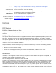
Appendix A Cross-Zoning Note: Cross-Zoning is not recommended for exit/entry zones. Each zone has the ability to individually protect the intended area. (e.g. motion detector patterns overlap). Cross-Zone (Alarm Verify) refers to two different Group 10-20 sensors that must be tripped within four minutes of each other to report an alarm to the central station. The diagram in Figure 23 below shows the path of a person walking from the kitchen to the living room.
Appendix A 013 Attic 053 Downstairs 093 Interior 133 Patio 173 Temperature 213 S 014 Auxiliary 054 Door 094 Intrusion 134 Pet 174 Test 214 T 015 Away 055 Driveway 095 Invalid 135 Phone 175 Time 215 U 016 Baby 056 Duct 096 Is 136 Please 176 To 216 V 017 Back 057 Duress 097 Key 137 PM 177 Touchpad 217 W 018 Bar 058 East 098 Kids 138 Police 178 Trouble 218 X 019 Basement 059 Energy Saver 099 Kitchen 139 Pool 179 Unbypass 219 Y 020 Bathroom 060 Enter 100 Latchk
Appendix A Menu name & (Default) Shortcut no. AC Failure (Off) 05010 Account No.
Appendix A Menu name & (Default) Shortcut no.
Appendix A Menu name & (Default) Shortcut no. Pager Phone 3 (None) 0140 Phone Test (On) 02000 Phone Test Freq.
Appendix A Menu name & (Default) Shortcut no.
Appendix A Menu name & (Default) Shortcut no.
Appendix A Exterior Siren 016 Interior Siren 017 AVM Trip (pulse) 018 Table 14: Sensor group event trigger numbers Sensor group. Trigger No.
Appendix A Group 29 in alarm 093 Group 32 in alarm 096 Group 33 in alarm 097 Group 34 in alarm 098 Group 35 in alarm 099 Table 15: Sensor number event trigger numbers Zone/sensor number State Trigger No. State Trigger No.
Appendix A Table 16: System feature event trigger numbers Feature State Trigger No.
Appendix A yes 1 yes 1 no siren time yes 1 no sustained yes 1 yes 1 yes 1 yes 1 no 5 09 2 10 3 11 3 minutes yes 4 momentary 12 yes 4 3 minutes 5 13 yes 4 siren time 2 14 yes 4 3 15 sustained Notes for Table 17 Response Numbers Note: The mechanical lifetime of the relay may be exceeded if an output is set up for a siren tracking response and a pulsing siren (auxiliary or fire) is active for long time periods.
Appendix B Programming mode menus and settings Use the following graphics to follow programming modes and menus.
Appendix B 104 Concord Express Installation Instructions
Appendix B Concord Express Installation Instructions 105
Appendix B 106 Concord Express Installation Instructions
Appendix C Software release notes and specifications Software Version 1.73 The following features were changed/added for software version 1.73. Downloader Code • If the Dealer Code (0002) is set, the Installer Code (0001) can’t view or edit the Downloader Code (0000) • Downloader Code and CS Phone Numbers (0100/0110) are NOT reset by a memory clear operation using the Installer Code if the Dealer Code has been set.
Appendix C Central Station Reports • An exit error event now sends an Entry/Exit Alarm and Exit Error reports to the central station. In CID format the report is: (CID: 457,user# and 134,zone#) IN SIA format the report is: (SIA: EE,user# and BA,zone#) Entry Delay • During Entry Delay the system can now be disarmed by entering a valid access code only. 1 + CODE is no longer required, but will still work. • The low limit and default setting on Entry Delay has been changed from 32 to 30 seconds.
Appendix C • The panel will recognize the extended version information request from the downloader and will respond with the extended version response message used by Enterprise. • An OEM code can be set that will prevent a standard version Toolbox or Enterprise from communicating with the panel. These panels can only be downloaded by a version of Enterprise that supports the panel’s specific OEM code. Smoke Verify • Smoke Verify (0900) is now implemented for RF smokes as well as hardwire smokes.
Appendix C Auxiliary power output 12 V @ 750 mA, current limited Dimensions 11 in. (28 cm) x 9 in. (23 cm) x 3.0 in. (7.