Yes, you can.
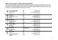
How can you get in touch with Invacare®? If you have any questions or need support, please contact your authorised Invacare® Dealer, who has the necessary know-how and equipment plus the special knowledge concerning your Invacare® product, and can offer you all-round satisfactory service. Should you wish to contact Invacare® directly, you can reach us in Europe at the following addresses and phone numbers.
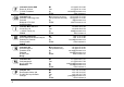
Invacare® Poirier SAS Route de St Roch F-37230 Fondettes France : Fax: @: WWW: Invacare® Ltd Pencoed Technology Park Pencoed Bridgend CF35 5AQ United Kingdom (Customer services): Fax (Customer services): @: WWW: Invacare Mecc San s.r.l. Via dei Pini, 62 I - 36016 Thiene (VI) ITALIA : Fax: @: WWW: +39 0445 38 00 59 +39 0445 38 00 34 italia@invacare.com www.invacare.it Invacare Ireland Ltd.
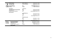
Återförsäljare: Invacare® AB Fagerstagatan 9 S-163 91 Spånga Sverige (Kundtjänst): Fax (Kundtjänst): @: @: WWW: Tillverkare: Invacare® Deutschland GmbH Kleiststraße 49 D-32457 Porta Westfalica Deutschland MÖLNDAL : Fax: @: Eastern european countries European Distributor Organisation (EDO) Kleiststraße 49 D-32457 Porta Westfalica Deutschland +46 (0)8 761 70 90 +46 (0)8 761 81 08 sweden@invacare.com finland@invacare.com www.invacare.se +46 (0)31 86 36 00 +46 (0)31 86 36 06 ginvacare@invacare.
Table of Contents Chapter 1 Introduction 1.1 1.2 1.3 1.4 1.5 2 6 6 16 General safety notes ...............................................................................................................16 Safety information with regard to care and maintenance ...................................................19 Safety information on electromagnetic interference ...........................................................20 Safety information on driving and freewheel mode...............................
6.1 7 Operating Console 7.1 7.2 7.3 7.4 7.5 7.6 8 Disengaging Motors ................................................................................................................31 Adjustment facilities 8.1 8.2 8.3 8.4 8.5 8.6 8.7 8.8 8.9 8.10 8.11 32 Operating Console Arrangement ...........................................................................................32 7.1.1 Status Display.........................................................................................................
.11.2 Removing the rollator bracket.......................................................................................64 8.11.3 Positioning the rear reflector.........................................................................................64 9 Electrical system 9.1 9.2 Electronics protection system ...............................................................................................66 9.1.1 The main fuse ..............................................................................
1 Introduction Dear user, First we would like to thank you for purchasing our product! We hope you will enjoy your new Scooter. This manual contains important hints and information on: • Safety • Operation • Care and maintenance. Please take care to read the operating manual thoroughly before starting out on your first journey. This product has been designed to fit the needs of different types of users with different requirements.
This manual contains copyrighted information. It may not be reproduced or copied in whole or in part without the prior written consent of Invacare® or its authorised representative. It may also contain information that pertains to models sold only in certain countries. In this case the information will be clearly marked as pertaining to a particular country-specific version. We reserve the right to make any alterations on the grounds of technical improvements. 1.
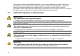
RISK OF CRUSHING! This symbol warns of a risk of crushing caused by being careless with heavy components. • Always follow the instructions to avoid injury to the user or damage to the product. Wear eye protection This symbol refers to the requirement for wearing eye protection, for example when working with batteries. • You must wear safety goggles when this symbol is displayed. Wear protective gloves This symbol indicates the requirement to wear protective gloves, for example when working with batteries.
1.2 Important symbols found on the vehicle This product has been supplied from an environmentally aware manufacturer. This product may contain substances that could be harmful to the environment if disposed of in places (landfills) that are not appropriate according to legislation. • The 'crossed out wheelie bin' symbol is placed on this product to encourage you to recycle wherever possible. • Please be environmentally responsible and recycle this product through your recycling facility at its end of life.
This mobility device may not be used as a vehicle seat! • This mobility device does not fulfill the requirements of ISO 7176-19:2001 and may not under any circumstances be used as a vehicle seat or to transport the user in a vehicle! • Using a mobility device that does not fulfill these criteria as a vehicle seat can lead to severe or fatal injuries in the event of a traffic accident! This symbol indicates the charging socket of the scooter.
1.3 Type classification and permissible use This vehicle was designed for persons whose ability to walk is impaired, but who are still in terms of their eyesight and physically and mentally able to operate an electric vehicle. It has been classified as a mobility product in Class C (outdoors) in accordance with EN 12184. Because of its size it is less suitable for use in indoor environments, but has a longer driving range and the ability to overcome larger and more difficult obstacles in outdoor settings.
The fact that we estimate a life expectancy for this product does not constitute an additional warranty.
2 Safety notes READ WELL BEFORE OPERATION! 2.
Danger of injury if the On/Off Button is pressed while the vehicle is in motion, due to it coming to an abrupt, sharp stop! • If you have to brake in an emergency, simply pull the handbrake until the scooter comes to a halt! Only switch the vehicle off while in motion as a last resort! Danger of injury if the scooter is transported in another vehicle with the occupant seated in it! • Never transport the scooter with the occupant seated in it! Danger of injury if maximum permissible load is exceeded! • Do no
Danger of injury by moving parts! • Make sure that no injury is incurred by moving parts of the scooter, like wheels or a Seat Lifter, especially when children are around! Risk of injury from hot surfaces! • Do not leave the mobility device in direct sunlight for prolonged periods. Metal parts and surfaces such as the seat and armrests can become very hot.
2.2 Safety information with regard to care and maintenance Danger of accident and loss of guarantee if maintenance is insufficient! • For reasons of safety and in order to avoid accidents which result from unnoticed wear, it is important that this electric mobility product undergoes an inspection once every year under normal operating conditions (see inspection plan contained in service instructions).
2.3 Safety information on electromagnetic interference This electric vehicle was successfully tested in accordance with International standards as to its compliance with Electromagnetic Interference (EMI) regulations. However, electromagnetic fields, such as those generated by radio and television transmitters, and cellular phones can influence the functions of electric vehicles.
2.4 Safety information on driving and freewheel mode Danger of injury if the vehicle tips over! • Only ever negotiate gradients up to the maximum tilt-resistant gradient and only with the backrest in an upright position, and the seat lifter in the lowest position (if installed)! • Only ever drive downhill at a maximum of 2/3rds of the top speed! Avoid abrupt braking or accelerating on gradients! • If at all possible, avoid driving on slippery surfaces (such as snow, gravel, ice etc.
Danger of injury if the vehicle tips over! (Continued) • Never use the vehicle to transport more than one person! • Do not exceed the maximum permissible load! • When loading the vehicle, always distribute the weight evenly! Always try to keep the centre of gravity of the vehicle in the middle, and as close to the ground as possible! • Note that the vehicle will brake or accelerate if you change the Driving Speed while it is in motion! Danger of injury if you collide with an obstacle when driving through na
CAUTION: it may be difficult to turn in front of a lift or building entrance because the scooter turning circle may not necessarily comply with building standards! • Always be aware of the limitations of your scooter, particularly the turning circle capabilities when entering a building or a lift.
3 24 Key features 1) Disengaging lever 2) Unlocking lever for sliding seat rails (front right below seat) 3) Unlocking lever for swivelling and removing seat (left under the seat, not visible in picture) 4) Operating console 5) Brake lever (right-hand lever) 6) Lever for adjusting steering column inclination (left-hand lever, not visible in picture).
4 The position of the labels on the product 1) Identification of charger socket (left-hand side of steering column, not visible in picture) 2) Identification label sticker on the chassis at the rear 25
3) Manufacturer label on the chassis at the rear 4) Distributor label on the chassis at the rear 5) Identification of HD version (CometHD only) 6) Identification of the position of the springs on the chassis at the front and rear (CometHD only) 7) Battery label under the cover at the rear The symbols on the labels are explained in section "Important symbols found on the vehicle" on page 12.
5 Driving 5.1 Getting in and out The armrests can be swivelled upwards to assist getting in and out. The seat can also be rotated to assist getting in and out. • Lift the detent lever (1) up. • Turn the seat to the side. Information on turning the seat The detent automatically engages again after 45°.
5.2 Before driving for the first time... Before you take your first trip, you should familiarise yourself well with the operation of the vehicle and with all operating elements. Take your time to test all functions and driving modes. NOTE: If installed, make sure to properly adjust and use the postural belt each time you use the wheelchair. Sitting Comfortably = Driving Safely Before each trip, make sure that: 28 • You are within easy reach of all operating controls.
5.3 Taking Obstacles You can find information about maximum obstacle heights in the chapter entitled "Technical specifications" from page 84. CAUTION: Danger of Tipping Over! • Never approach obstacles at an angle but at 90 degrees as shown below. • Put your backrest into an upright position before climbing an obstacle. Driving up over an obstacle • Correct Approach the kerb or obstacle slowly head-on.
5.4 Driving up and down gradients For information concerning the maximum safe slope, please see chapter "Technical specifications" starting on page 84.
6 Pushing the scooter by hand The motors of the scooter are equipped with automatic brakes, preventing the scooter from rolling away out of control when the power supply is switched off. When pushing the scooter, the magnetic brakes must be disengaged. 6.
7 Operating Console 7.
7.1.1 Status Display NOTE: The ON/OFF diode is used as a fault display (status display). Chapter "Error Codes and Diagnostic Codes" on page 42 contains an explanation of the error codes. 7.1.2 Battery Charge Display • • • All diodes illuminate: maximum driving range Only red and yellow diodes illuminate: reduced driving range. Recharge the batteries at the end of your journey. Only red LEDs illuminate/blink, electronics beeps 3x: battery reserve = severely restricted driving range.
7.2 Driving the Scooter WARNING: Danger from the unintended rolling of the vehicle! When stopping the vehicle, the drive lever needs to return entirely to the middle position to activate the electromagnetic brakes. If there is any obstruction stopping the lever from returning to the middle position, the electromagnetic brakes cannot be activated. This can lead to the vehicle rolling unintentionally. • Please make sure that the drive lever is in the middle position, if the vehicle is to remain stationary.
CAUTION: any changes to the drive program can affect the driving characteristics and the tipping stability of the vehicle! • Changes to the drive program may only be carried out by trained Invacare® specialist dealers! • Invacare® supplies all mobility products with a standard drive program ex-works. Invacare® can only give a warranty for safe vehicle driving behaviour - especially the tipping stability for this standard drive program! NOTE: • To brake quickly, simply let go of the driving lever.
The electronic system must be switched off in order to activate or deactivate an acoustic signal for particular functions, and a particular keystroke combination needs to be entered when switching on again. After a signal for a particular function has been successfully activated/deactivated, a combination of LEDs on the battery charge display will blink as a confirmation.
The keystroke combinations and LED codes for various options are as follows: Function: Keystroke combination Acoustic signal at "Lighting" + "direction low battery capacity indicator left" Acoustic signal when direction indicators actuated "Lighting" + "direction indicator right" LED(s) Condition D1 deactivated D1+D2 activated D3 deactivated D3+D4 activated Acoustic signal "Lighting" + "hazard lamps" D5 when hazard lamps actuated D5+D6 deactivated Acoustic signal when reverse gear actuated
Activating or deactivating an acoustic signal Please proceed as follows to activate or deactivate an acoustic signal for a particular function: 1) Switch off the electronic system. 2) Enter the keystroke combination and hold. 3) Switch on the electronic system 4) Wait two seconds until the appropriate blink code is displayed on the battery charge display, then release the keys. Do not hold the keystroke combination down for more than five seconds.
7.4 Activating and Deactivating Speed Reduction During Bend Travel Your Scooter is fitted with automatic speed reduction which is activated as standard when the Scooter is switched on. This function lowers the Scooter's speed as soon as you start driving round a bend. It is primarily designed for inexperienced users who may feel unsure of the Scooter's dynamic driving behaviour in a bend. If, however, you are an experienced user, you may wish to deactivate this function.
7.5 Diagnosis and fault repair The electronic system offers diagnostic information to support the technician during the recognition and rectification of faults on the Scooter. If there is a fault, the status display blinks several times, pauses, then blinks again. The type of fault is displayed by the number of blinks in each group, which are also known as the "blink code". The electronic system reacts differently depending on the seriousness of the fault and its effect on user safety.
7.5.1 Error diagnosis If the Scooter shows a failure, please use the following guide to locate the fault. NOTE: Before making any diagnosis, ensure that the Scooter has been switched on at the keyswitch. If the status display is OFF: check whether the keyswitch is SWITCHED ON. Check whether all cables are correctly connected. If the status bar indicator is BLINKING: count the number of blinks and then proceed to the next section.
7.6 Error Codes and Diagnostic Codes Blink code 1 2 3 Fault Consequence for the Scooter Battery must be Continues to • charged drive Battery voltage too Stops driving • low • Battery voltage too Stops driving high • • 42 Comments The batteries are discharged. Charge the battery as soon as possible. The batteries are depleted. Charge batteries. If you switch the Scooter off for a few minutes, the battery can often recuperate to such a stage that a short journey is still possible.
Blink code 4 Fault Power time exceeded Consequence for the Scooter Stops driving • • 5 Brake failure Stops driving • • • 6 No neutral position Stops driving when switching Scooter on. • • Comments The maximum current was exceeded over too long a period, probably because the motor was overloaded or has been working against an immovable resistance. Switch the scooter off, wait a few minutes and then switch on again. The electronic system has determined a motor short-circuit.
Blink code 7 Fault Fault in speed potentiometer Consequence for the Scooter Stops driving • • 8 Motor voltage error Stops driving • 9 Miscellaneous internal fault Push/freewheel mode error Stops driving • Stops driving • 10 44 Comments The drive lever electronics could be faulty or incorrectly connected. Check the cabling for open or short-circuited circuitry. Potentiometer is not correctly adjusted. Put the potentiometer into the centre position.
8 Adjustment facilities 8.1 Moving the seat position forwards or backwards The disengaging lever for adjusting the seat is located front right below the seat • Pull the lever (1) to disengage the seat. • Slide the seat forwards or backwards into the required position. • Let go the lever again to lock the seat into its required position.
8.2 Adjusting the armrest width The hand wheels for releasing the armrests are located under the seat (1). 46 • Turn the hand wheels to loosen the fixing for the armrest. • Adjust the armrests to the required width.
8.3 Adjusting the armrest height Requirements: • Phillips screwdriver • Use the screwdriver to loosen and remove the armrest fixing screw. • Adjust the armrests to the required height. • Reposition the screw and tighten again.
8.4 Adjusting backrest angle The lever (1) for adjusting the backrest angle is located on the right of the seat. • 48 Pull the lever and adjust the backrest to the required angle by leaning forwards or backwards.
8.5 Adjusting the lordosis supports (CometHD only) The lordosis support is the outward swell of the backrest which supports the lumbar region of the spine. You can regulate the strength of the outward swell using an air pump to fit it individually. Swelling the lordosis support more • Ensure that the air vent screw (1) is closed fully clockwise. • Pump air into the lordosis support using the rubber ball (2). The lordosis support will swell outwards more.
8.6 Disengaging the seat to rotate it or remove it The seat can be turned to one side to make getting in and out of the scooter easier. The seat is also easier to remove from this position. The lever for disengaging the seat is located under the seat (1) on the left. 50 • Pull the lever forwards to disengage the seat. • Turn the seat to the side. • If you want to remove the seat, hold it firmly by the backrest and front edge and remove it upwards.
8.7 Adjusting the seat height manually Requirements: • 2x open-ended spanners 17 mm • Remove the seat • Remove the battery and motor compartment cover. • Remove the seat pillar locking bolt using both openended spanners. • Adjust the seat height. • Reinsert the bolt and tighten.
8.8 Actuate the seat lifter (option) The rocker switch (1) for adjusting the seat lifter is located on the steering column. • 52 Press the switch up or down. The seat lifter will raise or lower.
8.9 Postural belts A postural belt is an option which can either be fixed to the wheelchair ex-works or can be retrofitted by your specialist dealer. If your wheelchair is fitted with a postural belt, your specialist dealer will have informed you about fitting and usage. The postural belt is used to help the wheelchair user keep an optimum sitting position.
8.9.2 54 Adjusting the postural belt correctly • Ensure that you are sitting correctly, which means that you are sitting right at the back of the seat, your pelvis is positioned erect and as symmetrically as possible, not to the front, to the side or at one edge of the seat. • Position the postural belt so that your hipbones can be easily felt above the belt. • Adjust the belt length using one of the adjustment aids described above.
8.9.3 Fixing the containment belt to the scooter Requirements: • jaw spanner 12 mm • jaw spanner 13 mm The fixing points (1) for attaching the belt are located under the seat (the figure shows only the left hand side).
• Take hold of the belt mounting and hold it in front of the hole in the fixing. • Position the bolt (1), screw the nut on from the other side and tighten with a jaw spanner. • Repeat the same procedure on the other side of the seat. Check to ensure that the nut is tightened properly on the bolt.
8.10 Adjusting the suspension The Comet suspension can be individually adjusted. These adjustments should only be carried out by trained specialists. Please contact your authorised Invacare specialist dealer. 8.10.1 Comet and CometAlpine Adjusting the suspension harder • Rotate the adjustable spring plate (1) clockwise when viewed from below in order to adjust the suspension harder.
Rear springs Meanings of symbols on sticker (1) - = suspension harder (2) + = suspension softer 59
The works setting for the lever is the middle position (1). The suspension can be adjusted harder or softer in four levels. Adjusting the suspension harder 60 • Rotate the lever to the left to adjust the suspension harder. • The fourth level (2) is the hardest suspension.
Adjusting the suspension softer 8.11 • Rotate the lever to the right to adjust the suspension softer. • The fourth level (3) is the softest suspension. Rollator bracket Your scooter can be fitted with an optional rollator bracket. Only the following rollators, which have been approved by Invacare, can be transported using this bracket: • Dolomite Jazz 600 • Dolomite Legacy 600 • Invacare Banjo P452E/3 The maximum permitted rollator weight is 9 kg.
CAUTION! Risk of tipping as a result of altered center of gravity. The center of gravity of the scooter shifts towards the back as a result of attaching the rollator. The maximum safe angle of incline is thereby reduced by up to 2°. • Please note that gradients that you would normally be able to negotiate may now be too steep and the scooter could tip. Do not attempt to climb or descend such gradients. 8.11.
Dolomite Legacy 600 Invacare Banjo P452E/3 63
8.11.2 Removing the rollator bracket • Loosen the screws (1). • Pull the rollator bracket out of the fixtures. 8.11.3 Positioning the rear reflector CAUTION! Risk of accident due to poor visibility. If you wish to use your wheelchair on public roads and a rear reflector is required by national legislation, then the rollator bracket may not cover the rear reflector. • Make sure that the rear reflector is mounted in such a way that a sufficient amount of the reflective area is visible.
• Position the rear reflector as shown in the drawing.
9 Electrical system 9.1 Electronics protection system The vehicle's electronics are equipped with an overload-protection system. If the motors are put under considerable strain for a longer period of time (for example, when driving up a steep hill) and especially when the ambient temperature is high, then the electronic system could overheat. In this case the vehicle's power is reduced gradually until it finally comes to a halt.
9.1.1 The main fuse The entire electric system is protected against overload by two master fuses. The master fuses are mounted on the positive battery cables. NOTE A defective main fuse may be replaced only after checking the entire electric system. An Invacare® specialised dealer must perform the replacement. You can find information on the fuse type in chapter "Technical specifications" starting on page 84. 9.2 Batteries 9.2.
NOTE The batteries supplied with your electric vehicle are not hazardous goods. This classification is based on the German GGVS Hazardous Goods Road Transport Ordinances, and the IATA/DGR Hazardous Goods Rail Transport / Air Transport Ordinances. Batteries may be transported without restrictions, whether by road, rail or by air. Individual transport companies have, however, guidelines which can possibly restrict or forbid certain transport procedures.
9.2.2 Charging the batteries • Make sure you read and understand the battery charger's User's Manual, if supplied, as well as the safety notes on the front and rear panels of the charger! WARNING! Risk of explosion and destruction of batteries if the wrong battery charger is used! • Only ever use the battery charger supplied with your vehicle, or a charger that has been approved by Invacare®.
The charging socket is located on the left of the steering column Connecting the battery charger • Switch off the Scooter. • Push the protective cap on the side of the charging socket to the side. • Connect the battery charger to the Scooter. • Connect the battery charger to the mains. Disconnecting the battery charger from the Scooter 70 • First unplug the battery charger from the mains. • Then unplug the battery charger from the Scooter.
9.2.
9.2.3.1 Removing the batteries Requirements: • Open spanner, 11 mm. 72 • Remove the seat. • Remove the battery and motor compartment cover. • Unplug the battery connecting plug (1). • Release the battery holder strap. • Remove the batteries.
• Loosen the blue cable on the negative battery terminal with the open-ended spanner, and remove the cable. • Loosen the red cable battery clamp on the positive battery terminal with the open-ended spanner, and remove the cable. • Repeat the procedure for the other battery NOTE: Replacing new batteries takes place in reverse order.
9.2.3.2 How to handle damaged batteries correctly WARNING: Corrosion and burns from acid leakage if batteries are damaged! • Remove clothes that have been soiled by acid immediately. After contact with skin: • Immediately wash affected area with lots of water. After contact with eyes: • Immediately rinse eyes under running water for several minutes; consult a physician. • Always wear safety goggles and appropriate safety clothing when handling damaged batteries.
10 Care and maintenance The term „Maintenance“ means any task performed to ensure that a medical device is in good working order and ready for use as intended. Maintenance encompasses different areas, such as everyday care and cleaning, inspection checks, repair tasks and refurbishment. NOTE: Have your vehicle checked once a year by an authorised Invacare® dealer in order to maintain it's driving safety and roadworthiness. 10.
indicated or contact your authorised Invacare® dealer. A more comprehensive list of inspection checks and instructions for maintenance work can be found in the Service Manual for this device, which can be obtained from Invacare®. That Manual, however, is intended to be used by trained and authorised service technicians, and describes tasks which are not intended to be performed by the user. Seat and backrest padding: • Check for perfect condition.
Cleaning: • Clean all parts carefully. 11 When necessary Repair instructions The following are instructions on repairs that can be performed by the user. For the specifications of spare parts please see "Technical specifications" on page 84, or consult the Service Manual, available from Invacare® (in this connection please see the addresses and phone numbers in section "How can you get in touch with Invacare®?" on page 3). In case you require assistance, please contact your Invacare® Dealer. 11.
11.1.1 Mending punctures (pneumatic tyres of type 4.00 - 5) Requirements: • Open spanner, 17 mm. • Rubber hammer • Raise the vehicle and place wooden blocks underneath to support it. • Remove the wheel locknut (1) with a 17 mm open-ended spanner. • Remove the wheel by tapping it gently with the rubber hammer on the rear face to carefully loosen it from the axle. Problems when removing wheel? It may be necessary to use a special tool Please ask your Invacare® dealer to help you.
11.1.1.1 Repairing punctured tyres Requirements • inner tube repair set or a new inner tube • talcum powder • open-ended spanner, 12 mm • Remove valve cap. • De-inflate the tyre by pressing in the centre valve pin. • Loosen the 4 bolts (1) with the socket spanner and remove them. • Remove both wheel rim halves out of the tyre and remove the inner tube. • Repair the inner tube and refit in the wheel, or replace it with a new inner tube.
Did the old inner tube get wet during the repair? If you repaired the old inner tube and reused it, and it became wet during repair, it is much easier to refit it into the wheel if you powder it lightly with talcum powder. 80 • Refit the wheel rim parts from outside into the tyre. • Pump up the tyre lightly. • Reinsert the nuts and bolts which hold the wheel rim together and tighten fully. • Make sure that the tyre is properly located on the wheel rim.
12 Transport CAUTION: Danger of death or serious injury to the mobility device user and potentially any other nearby occupant of the vehicle, if a mobility device is secured using a 4-point tie-down system available from a third party supplier and the unladen weight of the mobility device exceeds the maximum weight for which the tie-down system is certified! • Make sure the weight of the mobility device does not exceed the weight for which the tiedown system is certified.
12.
12.2 Transporting the wheelchair without occupants CAUTION: Injury hazard! • If you are unable to fasten your electric wheelchair securely in a transport vehicle, Invacare® recommends that you do not transport it! • Before transporting your wheelchair, make sure the motors are engaged and that the Joystick Box is switched off. Invacare® strongly recommends that you additionally disconnect or remove the batteries. See "Removing the batteries" on page 72.
14 Technical specifications The technical information provided hereafter applies to a standard configuration or represents maximum achievable values. These can change if accessories are added. The precise changes to these values are detailed in the sections for the respective accessories.
Tyres Tyre type Tyre type • 4.00 - 5 pneumatic The recommended maximum tyre pressure in bar or kpa is marked on the side wall of the tyre or the rim. If more than one value is listed, the lower one in the corresponding units applies. (Tolerance = -0.3 bar,1 bar = 100 kpa) • 13" puncture-proof Driving characteristics Speed Min. braking distance Max. safe slope ****** Max.
Dimensions Overall width (armrest adjustment range) Total height Seat width Seat depth Seat height Backrest angle Armrest height Weight Kerb weight • • • • • • Batteries Seat unit Payload Max. payload Axle loads Max. front axle load Max. rear axle load Comet Alpine Comet • • • • HD • 1290 mm • 660 mm • 535 mm 1255 mm 510 mm 485 mm 440 / 465 / 490 / 515 mm 95° ... 145° 200 ... 245 mm • 95° ... 120° Alpine Comet • 3-wheel: 133 kg • 4-wheel: 136 kg Component weights Chassis 86 Comet • 630 ...
*** Note: The drive range of an electric wheelchair is strongly influenced by external factors, such as the charging state of the batteries, surrounding temperature, local topography, road surface characteristics, tyre pressure, weight of driver, drive style and use of batteries for lighting, servos etc. The specified values are theoretical maximum achievable values measured according to ISO 7176-4:2008.
15 Inspections Performed It is confirmed by stamp and signature that all jobs listed in the inspection schedule of the Service and Repair Instructions have been properly performed. The list of the inspection jobs to be performed can be found in the Service Manual which is available through Invacare®.
Hersteller / Manufacturer / Fabricante / Proizvođač: CHIEN TI ENTERPRISE CO. LTD. No. 13, Lane 227, Fu Ying Road Hsin Chuang, Taipei, Taiwan R.O.C.
Tel: (44) (0) 1656 - 77 62 22, Fax: (44) (0) 1656 - 77 62 20 Sweden, Danmark, Nederland Invacare REA Växjövägen 303 S-343 71 DIÖ Sweden Tel: (46) (0) 476 - 535 00, Fax: (46) (0) 476 - 535 99 Deutschland, Eastern Europe Invacare Deutschland GmbH Kleiststraße 49 32457 Porta Westfalica Deutschland Tel: (49) (0) 5731 - 754 0, Fax: (49) (0) 5731 - 754 52 191 90
English Order No. of this Manual: 1514597.