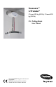
Invacare® I-Transia™ I-Transia 205 kg (450 lb), I-Transia 250 kg (550 lb) EN Ceiling Hoist User Manual This manual MUST be given to the user of the product. BEFORE using this product, read this manual and save for future reference.
©2013 Invacare®Corporation All rights reserved. Republication, duplication or modification in whole or in part is prohibited without prior written permission from Invacare. Trademarks are identified by ™and ®. All trademarks are owned by or licensed to Invacare Corporation or its subsidiaries unless otherwise noted.
6.1 Contents 6.2 1 2 3 4 5 6 General . . . . . . . . . . . . . . . . . . . 4 1.1 Symbols. . . . . . . . . . . . . . . 4 1.2 Intended Use . . . . . . . . . . . 4 1.3 Conditions for Use . . . . . . 5 1.4 Service Life . . . . . . . . . . . . 5 1.5 Features . . . . . . . . . . . . . . 5 Safety. . . . . . . . . . . . . . . . . . . . . 6 2.1 General Guidelines. . . . . . . 6 2.2 Operating Information . . . . . . . . . . . . 6 General . . . . . . . . . . . . . 6 Pinch Points and Positioning . . . . . . . .
I-Transia™ 1 General 1.1 Symbols Signal words are used in this manual and apply to hazards or unsafe practices which could result in personal injury or property damage. See the information below for definitions of the signal words. WARNING! – Warning indicates a potentially hazardous situation which, if not avoided, could result in death or serious injury. CAUTION! – Caution indicates a potentially hazardous situation which, if not avoided, may result in property damage or minor injury or both.
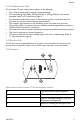
General 1.3 Conditions for Use The use of the I-Transia ceiling hoist is subject to the following: • • The I-Transia should only be used by trained personnel. The safe working load (SWL), 205 kg (450 lbs) or 250 kg (550 lbs), must not be exceeded. Refer to 2.3 Load Limits, page 8 . The instruction offered by Invacare to all customer groups in connection with the purchase of a ceiling-mounted hoist has been received. The caregiver pays attention to the well-being of the user when using the hoist.
I-Transia™ 2 Safety 2.1 General Guidelines WARNING! – Read and understand these instructions. DO NOT use this product without reading and understanding these instructions. If you need help with these instructions, contact a healthcare professional or an Invacare dealer. Otherwise injury or damage may occur. ACCESSORIES WARNING – Invacare products can only be used with accessories made by Invacare. Accessories not made by Invacare have not been tested by Invacare.
Safety WARNING! – The electronics may only be serviced by certified service technicians – For safety reasons the side cover may only be dismantled when the emergency stop is activated. – This product is mechanically protected against derailing and jamming. – The hand control is protected against water splashes (IPX4). DO NOT immerse the hand control in liquids, even for a short time. Avoid any contact with water or other liquids.
I-Transia™ 2.3 Load Limits Read the label which indicates the maximum load limits for each component. The component, e.g. hanger bar, lifting sling, etc. labelled with the lowest load limit determines the maximum load limit for the entire system. This maximum load limit must not be exceeded. Please note that the max load may change when different components are used, such as hanger bars, lifting slings, etc. 2.4 Power Supply I-Transia is equipped with a battery that requires regular recharging.
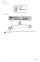
Safety 2.6 Product Labeling Hoist Only one of the weight limit labels are on the bottom of the hoist.
I-Transia™ Hand control Hanger Bar The hanger bar label is located near the end of the hanger bar, to the inside of the hooks.
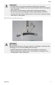
Setup 3 Setup 3.1 Included Items 1. 2. 3. 4. 5. 6. I-Transia hoist* Hand control Transformer Charging station Side covers Hanger bar *The hoist includes the lifting strap, carabiner and trolley. 3.2 Installing the Hanger Bar Before Use WARNING! Risk of Injury Pinch points are present on the strap carabiner B and fingers could be pinched. The hanger bar A can move suddenly and cause injury. – ALWAYS keep hands and fingers clear of moving parts to avoid injury.
I-Transia™ The hanger bar A can be installed to the lifting strap carabiner B without the use of tools. 1. 2. 3. 4. 5. Pull and hold the retainer C up toward the pin D. Move the pin and retainer down to open the carabiner B. Install the hanger bar A onto the carabiner. Release the retainer and pin. Before use, ensure the hanger bar is installed completely onto the carabiner and the retainer is in place, as shown in the figure. 3.
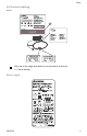
Operation 4 Operation 4.1 Indicator lamps and audio signals Status Off-stand by Indicator lamps Audio signals Possible I-Transia Functions Up Down Emergency Lowering Off All OK Green ü ü ü Low battery Yellow ü ü ü Fault on hoist Yellow Battery critical low Yellow Over load Green Beeps at button activation Beeps at button activation ü ü ü ü ü 4.2 Operating the Hoist The I-Transia is switched on automatically when a button on the hand control is pressed.
I-Transia™ 4.3 Charging the Battery The I-Transia battery charges when the hand control is placed in the charging station. The indicator lamp on the bottom of the hoist turns yellow if the charge status becomes low. Finish the current lift in progress and charge the batteries when finished. The hoist is charged when the indicator lamp on the bottom of the hoist is green. Always leave the hand control in the charging station when the I-Transia is not in use.
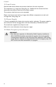
Operation The red strap A on the underside of the hoist B has the following functions: • • Emergency stop Emergency lowering Emergency stop Pull and release the red strap A to activate the emergency stop function if the hoist B does not stop or react to the hand control during use. Lifting/lowering functions are deactivated. Emergency lowering will not stop. The hoist will not function until the emergency stop is reset. The green lamp C will turn off.
I-Transia™ Emergency lowering The emergency lowering function is used to lower the patient if the hoist stops working. 1. 2. Pull and hold the red strap A to lower the patient. Release the red strap to stop lowering the patient. The emergency stop feature is activated when the strap is released. 3. 4. 16 If the hoist system needs service, contact your Invacare dealer for service. Reset the emergency stop to resume using the hoist. Refer to Resetting the emergency stop, page 17.
Operation Resetting the emergency stop The yellow reset button A pops out when the red strap B has been pulled. The hoist will not function until the emergency stop is reset. 1. 2. Press the yellow button on the bottom of the hoist to reset the emergency stop or lowering feature. Activate the hand control twice to resume use of the hoist.
I-Transia™ 5 Lifting the Patient 5.1 Sling Information WARNING! Invacare shall not be liable for damage or injury that may occur as a result of using slings made by other manufacturers. Invacare shall not be liable for damage or injury due to incorrect use of the sling or inadequate attention by the caregiver or user. – Use the sling that is recommended by the individual’s healthcare team for the comfort and safety of the individual that is being lifted.
Lifting the Patient 5.3 Lifting Information WARNING! Only personnel who have received training regarding the use of lifting equipment and fitting of slings should use the hoist. – Plan the move. Avoid leaving the user in the sling unattended. – The I-Transia lifts quickly. Before lifting, check that the user is completely free of his/her surroundings. – The user’s head, arms, hands and feet must not be in danger of becoming trapped. – Be careful with any tubes and wires that are attached to the user.
I-Transia™ 6 After Use 6.1 Transport and Storage Invacare recommends that the I-Transia is always transported and stored in the original packaging. For long term storage, the emergency stop must be activated. Refer to Emergency stop, page 15. This will prevent the discharge of the battery. The I-Transia should be stored as indicated by the packaging symbols in the table.
After Use Environmental Policy Statement Invacare is continuously working towards ensuring that the company's impact on the environment, locally and globally, is reduced to a minimum. It is Invacare’s goal to: • • • • Comply with the current environmental legislation (e.g.
I-Transia™ 7 Troubleshooting 7.1 Troubleshooting Table SYMPTOMS PROBLEM I-Transia hoist does not Emergency stop is activated. respond to the hand control’s keys. System does not have power or battery is discharged SOLUTION Check that the emergency stop is not activated. Check that the I-Transia has power supply and that the battery is recharged. Check that the transformer is switched on and connected to the charging station. Place the hand control in the charging station and recharge the I-Transia.
Maintenance 8 Maintenance 8.1 Safe Maintenance WARNING! Regular maintenance of patient lifts and accessories is necessary to assure proper operation. – Maintenance MUST be performed only by a certified technician. 8.2 Maintenance and Safety Inspection Service Interval At normal daily operation, a service check-up should take place every year, according to the Safety Inspection Checklist in the Service Manual.
I-Transia™ Daily Inspections The hoist should be checked each time it is used. Perform the following checks in addition to those performed in the annual service inspection. If you question the safety of any part of the lift, DO NOT use. Contact your Invacare dealer IMMEDIATELY. q Visually inspect the sling, hanger bar and lifting strap. Check all parts for damage or wear. If damage is found, DO NOT use. Contact your Invacare dealer IMMEDIATELY. q Check the emergency stop and emergency lowering function.
Technical Data 9 Technical Data 9.1 Typical Product Parameters Classification Non-permanent installation with out protective ground. Class II equipment Mobile equipment is class II equipment (marked with double-encased symbol) and can be connected to the mains direct by the user. Equipment is disconnected from the supply mains by detaching the mains plug from the wall outlet. Flammability Flammability This equipment is not suitable for use in the presence of flammable mixtures.
I-Transia™ Dimensions A B C D E, min F, min G 580 mm (22.8 in) 350 mm (13.8 in) 156 mm (6.1 in) 184 mm (7.2 in) 83 mm (3.3 in) 415 mm (16.3 in) 2500 mm (98.4 in) Depth of hoist 194 mm (7.6 in ) Safety Emergency stop Emergency lowering device Control of lifting strap Cut-off angle Yes Yes, electrical Yes 45° along the rail, 10° across the rail.
Warranty 10 Warranty 10.1 Limited Warranty — Europe Terms and conditions of the warranty are part of the general terms and conditions particular to the individual countries in which this product is sold. In order to comply with Health & Safety regulations and to ensure that Invacare employees are not exposed to the risk of infection, we must insist that all products returned for repair are thoroughly cleaned.
Notes
Notes
Notes
United Kingdom Invacare Limited • Pencoed Technology Park, Pencoed, Bridgend CF35 5AQ • Tel: (44) (0) 1656 776 222 • Fax: (44) (0) 1656 776 220 • www.invacare.co.uk • UK@invacare.com Ireland Invacare Ireland Ltd • Unit 5 Seatown Business Campus • Seatown Road • Swords • County Dublin – Ireland • Tel : (353) 1 810 7084 • Fax: (353) 1 810 7085 • www.invacare.ie • ireland@invacare.com Australia Invacare Australia Pty Ltd.
Manufacturer V. Guldmann A/S Graham Bells Vej 21–23A DK-8200 Aarhus N, Denmark EU Representative Invacare Limited Pencoed Technology Park Pencoed, Bridgend CF35 5AQ United Kingdom Invacare Corporation USA One Invacare Way Elyria, Ohio USA 44036–2125 800–333–6900 www.invacare.