FTA Communication Technologies IDLV-5000P 18 Duchscherstroos, L-6868 Wecker, Luxembourg Tel: +352 264 367 1 Fax: +352 264 313 68 e-mail: info@inverto.tv Web: www.inverto.
En IDLV-5000P Professional MPEG-2/ MPEG-4 AVC SD/HD Integrated Receiver Decoder User Manual Model IDLV-5000P
Table of Contents BEFORE USE THE DEVICE INTRODUCTION INSTALLATION Inspection Operating voltage The fuses Connecting up the device Power on the device NAVIGATING THE FRONT PANEL MENU STRUCTURE AND OPERATING THE DEVICE Inputs menu Outputs menu System menu FAQ TECHNICAL SPECIFICATIONS Input Output I/O interface General Accessory list 2 3 4 5 5 5 5 5 6 6 6 7 8 12 13 14 14 14 15 15 15
En 1. Before Use the Device Thank you for purchasing the IDLV-5000P series. This User Manual is written for operators/users of the IDLV-5000P Multi-Format Professional HDTV Processor to assist in installation and operation. Please read this user manual carefully before installation and use of the device For Your Safety This equipment is provided with a protective earthing ground incorporated in the power cord. The main plug shall only be inserted in a socket outlet provided with a protective earth contact.
2. Introduction The IDLV-5000P is full compliant with MPEG-2 (MP@ ML& MP@HL), H.264 and DVB-S2/S/-C/-T standards. With a wide choice of input options for all transmission mediums, the IDLV-5000P provides significant benefits and the maximum flexibility for professionals who wish to migrate their operations from MPEG-2 SD to H.264 HD. Equipped with 2 PCMCIA slots, it also supports various CA systems such as Irdeto, Conax, Viaccess, Cryptoworks, Mediaguard, and SECA, etc.
En 3. Installation 3.1 Inspection Open the packaging box, check if all accessories are in the box according to the packing list, and if the device has any visible damage, please contact the agent. 3.2 Operating Voltage Do not connect AC power until you have verified that the line voltage is correct and the proper fuses are installed. The device’s power supply is fitted with a wide-ranging power supply. It is suitable for supply voltages of 100-240 Vac -10% +6% at 50/60 Hz nominal.
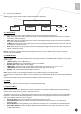
19. L-Audio-R1 20. Audio1 Group1 RCA audio output port AES/EBU and Balance Audio output port1 (need to use the RS232-to-XRL converting cable in accessories) Tuner signal loop through output port Tuner signal input 21. TUNER OUT 22. TUNER IN 3.5 Power On the Device Be sure the device is mounted into the rack properly and firmly, and the signal cables are connected well, then power can be applied to the device. The main socket and fuse are located at the rear panel of the device.
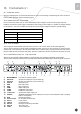
En 5.1 Inputs Menu There are four options: Status, DVB-S2, RSSI and Ethernet (optional): Inputs Status DVB-S2 RSSI Ethernet 5.1.1 Status Menu It contains four options, ASI1, ASI2, TUNER and IP IN, to show the status of signal input: ASI1: When signal from ASI1 input port is locked, it will display package format and code rate; if signal is not locked, it will show Unlock.
• • • • • • • • Multicast IP Addr: Enter the IP address of the multicast stream for the transport stream over IP. Multicase UDP Port: Enter the UDP port number of the TS over IP stream. Protocol: select the protocol for multicast: UDP or RTP. Output Smoothing: set the quality of TS which comes from the TS/IP input. Auto: the bit rate is variable. Disable: the unit let the TS pass by. Fixed Rate: the bit rate is fixed. TS Bit Rate: set the bit rate of the TS comes from the TS/IP input.
En 5.2.3 Decoder You can configure the parameters of Video and Audio of the program decoded by AV decoder. Status: OK or Alarms indicates the status of the decoder. You can use the key to check detailed information.
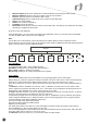
5.2.4 ASI1 You can configure the settings of ASI1 in this menu. ASI1 Source: Press the key and use the or key to roll up or down to select the signal source of ASI output, there are 5 type of signal source optional: 1. CI De-encrypted: the de-encrypted transport stream from CI functional block will be delivered to the ASI output port on the back panel. 2. TUNER: the transport stream from Tuner block will be delivered to the ASI output port on the back panel. 3.
En 5.2.8 Ethernet Note: this menu is showed only when the TS/IP streaming is installed and the board is set to “IP Out”, refer to section ‘Optional Function’ for how to set up. The TS/IP Ethernet connector could also be configured as the output of the transport stream over IP. The parameters listed below must be set to appropriate values for the network over which the transport stream over IP is broadcasted. Stream IP Addr: Enter the IP address for streaming IP output of the unit.
IPTV mode • • • Max Channels (<=6): you can configure the number of IPTV channel. The valid range goes from 0 to 6. After the configuration, you can use keys to roll up and down between the channels. Each channel could be configured independently. Channel x: ‘x’ means the channel number. Press key to go down to the sub-menu. There are 4 sub-menus: x-Multicast IP: Enter the IP address of the IP stream for the transport stream over IP output.
En • • • • Decoder version: show Decoder version FPGA version: show FPGA version TS/IP IN (or OUT) NIOS: it’s changed when TS/IP board is set to “IP Out” or “IP IN”. TS/IP IN (or OUT) FPGA: it’s changed when TS/IP board is set to “IP Out” or “IP IN”. 5.3.5 Factory Setting All the user configurable parameters will be set to the factory default settings, including IP address and the unit name. 5.3.6 Optional Function There are two submenus: 1.
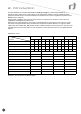
7. Technical Specifications Input DVB-S2 QPSK/8PSK Demodulation Input frequency range 950~2150MHz Input level -65~-25dBm Input impedance 75Ω Connector F Connector Symbol rate 5~45Msps for QPSK; 10~31Msps for 8PSK Rolling off factor 0.35 for QPSK; 0.35, 0.25, 0.2 for DVB-S2 Punctured rates DVB-S2 QPSK: 1/2,3/5,2/3,3/4,4/5,5/6,8/9,8/10 DVB-S2 8PSK: 3/5,2/3,3/4,5/6,8/9,9/10 DVB-S: 1/2,2/3,3/4,5/6,6/7,7/8 LNB Level 0, 13V, 18V 0/22K 0/22K DiSEqC DiSEqC 1.
En I/O Interface Tuner input/loop through Power supply socket RS-232 TS/IP Management ASI input ASI output SDI output HDMI output YPbPr output CVBS output AES/EBU 1× Input, 1×loop through output 3 pin inputs 1×9-pin D-sub male(for software update, Max Data Rate is 115200bps) TS over IP input/output (optional) Network management system, allowing parameter setting and software upgrade 2 x BNC Female 4 x BNC Female 2 x BNC Female, supports HD-SDI/SD-SDI, (one for back-up) optional 1(optional) 1 1×