
Operation Manual


6
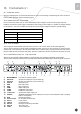
L-Audio-R119. Group1 RCA audio output port
Audio1
20. AES/EBU and Balance Audio output port1 (need to use the RS232-to-XRL converting
cable in accessories)
TUNER OUT21. Tuner signal loop through output port
TUNER IN22. Tuner signal input
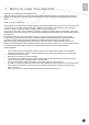
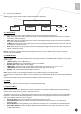
3.5 POWER ON THE DEVICE
Be sure the device is mounted into the rack properly and rmly, and the signal cables are connected well, then
power can be applied to the device. The main socket and fuse are located at the rear panel of the device.
When the device is powered on, verify that the display shows the following message:
Digital TV Processor (factory default unit-name)
IP: 10.10.60.148 (factory default IP Address for LAN access)
If no message is shown in the display or there is not light in the display, the device is defective and has to be
returned for servicing.
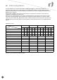
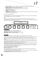
4. Navigating the Front Panel
POWER1. Power indicator, green light means power is OK
TUNER LOCK2. Tuner lock indicator, green light means signal is locked; if there is no light, which
means no signal input or wrong parameters setting.
ALARM3. Alarm indicator
LCD4. 2 × 20 character LCD
Operation button5. <LEFT> <UP> <DOWN> <RIGHT> <ENTER> <EXIT> buttons
<UP> <DOWN> buttons are used to up/down pages of menu or increase/decrease
value when edit numbers
<LEFT> <RIGHT> buttons are used to move cursor
<ENTER> button is used to enter sub menu or conrm operation
<EXIT> button is used to return previous menu or cancel operation
Common Interface6. PCMCIA Module slot
5. Menu Structure and Operating the
Device
The menu structure of the device is showed in below gure. After initialization is completed, press (ENTER)
button to enter main menu:
(1) Input Setup Set input parameters
(2) Output Setup Set output parameters
(3) System Set system parameters
Main Menu
Inputs
Outputs System
IDLV-5000P Professional MPEG-2/MPEG-4 AVC SD/HD Integrated Receiver Decoder
Enter Exit
Power T u ner Lock Alarm
1 2 3 4 5 6