
Technical Specifications

© Copyright 2020, Atlas Roong Corporation ATL-205562-05 12/20
#AtlasProtects AtlasRoofing.com
HIGHPOINT® INVISARIDGE™ EXHAUST VENT
INSTALLATION INSTRUCTIONS
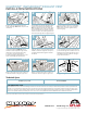
Remove ridge cap shingles from the entire
length of the ridge. Note: Delete Step 1 for new
construction.
Nail each additional section in the same manner
until entire ridge is covered. A chalk line may be
utilized to ensure vent alignment. Cut last piece
to length and install with original uncut end to
the outside.
Install new ridge cap in normal manner, using
2-1/2” roong nails, for 3/4” deck penetration or
penetration through the deck, whichever is less.
Nailing the ridge caps through the vent along
the nailing line will secure the vent. Shingles
may need to be trimmed.
Ridge-to-ridge application requires a mitre-cut
to maintain continuous ridge line appearance.
Ridge-to-roof application requires a mitre-cut
to maintain continuous ridge line appearance.
Cut along chalk lines. Remove roof sheathing.
Note: Slot should not be cut any closer than
within twelve (12) inches of gable end, hip
intersecting ridge.
For appearance (to blend with the roof line), it is
recommended that the HighPoint® vent be
installed the entire length of the ridge. Position
the rst piece at one end of the ridge. Using
2-1/2” nails, for 3/4” deck penetration or
penetration through the deck, which ever is less,
anchor vent through preformed nail holes.
Ridgepole Diagram
Ridgepole (1-1/2”)
Sheathing
1” Air
Opening
1” Air
Opening
2
1
/
4
” 2
1
/
4
”
Snap chalk line on both sides of the ridge and no
more than .750 (3/4) of an inch from the peak.
Note: If a ridgepole is present, cut a wider gap to
allow a minimum of 1/2” air gap on both sides of
the pole into the attic space - but do not remove
more than 2-1/4” of roof sheathing material from
either side of the ridge. Refer to ridgepole diagram.
7
Optional
8
Optional
1
2
3
5
6
4
Application and installation procedures are beyond the control of the seller or manufacturer. (Consequently, neither party shall be responsible for
failure of the product when not used in strict accordance to instructions and specications.)
Technical Specs
18 NFA sq. in. per ft. 48” PC LENGTH
UNIFORM BUILDING CODES
R806.2 Minimum area. The total net free ventilating area shall not be less than 1/150 of the area of the space ventilated except that the total area is permitted to be
reduced to 1/300, provided at least 40 percent and not more than 50 percent of the required ventilating area is provided by ventilators located in the upper portion
of the attic or rafter space. Upper ventilators shall be located not more than 3 feet (914 mm) below the ridge or highest point of space, measured vertically, with the
balance of the required ventilation provided by the eave or cornice vents. See the published International Residential Code for additional information.