® iOptron® iPolarTM Electronic Polar Scope Operation Manual Product #3339 Ver. 2.50 2021.1 iOptron reserves the rights to revise this instruction without notice. Actual color/contents/design/function of a product may differ from those described in this instruction manual.
1. Connect iPolar to a PC (1) Connect the iPolar Electronic Polar Scope (iPolar) to one of your computer USB port; (2) The iPolar has embedded driver. It will install the driver automatically if it is connected to the computer first time. It may take some time to install the firmware. A icon should be shown on Windows right bottom corner while firmware is installed. (3) Check the Windows Device Manager. There should be an iOptron iPolar under Camera 2.
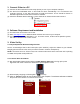
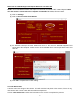
NOTE: If the software cannot connect to the camera, please check your computer camera settings. Make sure to change "camera privacy" settings to allow apps to use the camera. 3.3. Initial Settings Click on Settings to bring up Settings window. 3.4. Set Location and Atmospheric Parameters Enter Manually (1) Click on Change button (2) Enter location info, i.e., latitude and longitude number (GPS coordinates).
(3) Enter atmospheric parameters, i.e., temperature and barometric pressure. If the observation site is near equators (lower latitude, N10° ~S10°), or is at high elevation (3000 meter or higher above sea level), please enter the barometric pressure and temperature as precise as possible. Otherwise you may choose default atmospheric settings, just click on Default Atmospheric Parameters. The default value is 10°C and 101325Pa. (4) Click Confirm to complete the location setting.
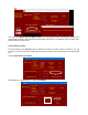
Read from an ASCOM Supported iOptron Mount for Location Info NOTE: You’ll need latest firmware and iOptron Commander, as well as .NET 4.8 and beyond. Make sure the mount is connected to the computer via ASCOM. Otherwise, this won’t work. (1) Click on Settings (2) Click on Read Location from Mounts (3) An ASCOM Telescope Chooser window will occur, if the mount is ASCOM supported and connected to the computer. Select correct mount ASCOM driver from the pull-down menu and click OK.
You may check Auto-Load Last Dark Frame box to load the dark frame automatically. However, we recommend to take the dark frame when performing polar align. If the software does not plate solve, please retake the Dark Frame. 3.6. Set Camera Center For most mounts, you DO NOT need to perform this step to set the Center of Camera. It is only needed if an iPolar cannot be rotated with the mount RA axis, such as SkyTracker and SkyTracker Pro. Click on Input Center of Camera, Enter 0480.0 in X and 0640.
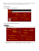
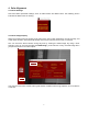
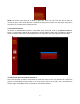
4. Polar Alignment 4.1. Check Settings Check the iPolar parameter settings, such as GPS location and Dark Frame. The following screen indicates the Dark Frame is missing. 4.2. Check Image Display When the mount RA axis is pointing to the pole region, the location parameters are set correctly, and a dark frame is taken, stars should be shown on the screen when the lens cover is removed. One can check the iPolar camera during day time by viewing the RAW image.
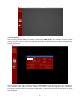
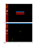
4.3. Plat Solving After checking camera settings and status, uncheck the RAW image. The software will start to Plate Solving the pole region. A real time image with white dots on black background will be displayed after imaging processing. Please check the real time instruction under the Connected box on top-right corner. If it displays “xx stars detected. Plate solve succeed!” There is no need to adjust the exposure time.
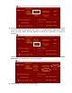
NOTE: the field of view (FOV) of an iPolar is about ±6°. So it can only cover the area of about 6° around the pole. If the mount RA axis is pointed far away from the pole, the plate solve may not be successful, or the pole will be jumping around. 4.4. Confirm Position 1 As shown in aforementioned picture, if the Plate Solve succeeds, click on “Confirm Position 1” button. A confirmation window will be popped up. Click on OK to confirm.
The software will display the virtual pole with a maroon circle and camera center a red cross. If the virtual pole is away from virtual pole and not in the iPolar FOV, an arrow will show where it is located.
4.6. Adjust Mount RA Axis Adjust the mount using altitude/azimuth adjustment screws to move the virtual pole (maroon circle) towards the center of camera (red cross). When they are close enough, the software will be in the zoom mode for easy adjustment. NOTE: It is suggested to set the mount to Zero Position so the virtual pole movement direction corresponds to the alt/azi adjustment.
4.7. Complete Polar Alignment When the circle overlaps the cross, they will change to green and the polar alignment is completed. 5.
(2) Move the mouse cursor to the starting corner of the area that you want to ignore, click the mouse button (3) Move to ending corner and click the mouse. A green rectangular will show on the screen. (4) Select another area as needed. (5) Click on END Draw to confirm, or Clear Mask to clear all the masks.
Specifications Field of View (FOV) ~ 13 degree Resolution 30 arcsec approx. Alignment Precision 30 arcsec Chip 1/3” CMOS Pixel Size 3.75µmX3.75µm Pixel Number 1.2MP (1280X960) Interface Mini USB2.0 Software iPolar Software Operation System Windows 7/8.1/10, 32bit or 64 bit, with Microsoft .NET Framework 4.8 installed Warranty One year limited The device specification may change without notice. Actual device may differ from this manual.