
Installation Guide

Page 3
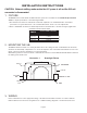
4. MOUNTING THE TBTS TEST ACCESSORY
Cut a single gang switch box into the ceiling tile adjacent to the fixture within reach of the ILB flex conduit marked
“B”. After mounting the switch box, connect flex to the box and route all leads inside the box. Refer to Illustration 1
for typical mounting. For proper operation, use only the accessory components provided with the unit. See Page 1
of the Instruction Manual.
5. LABELS
Attach the appropriate labels adjacent to the TBTS. Annotate Replacement Label with identical manufacturer part
number(s). The Caution and the Replacement labels must be on the fixture in a readily visible location to anyone
attempting to service the fixture.
6. WIRING THE A.C. INPUT
A. The ILB and A.C. driver MUST be on the same branch circuit.
B. The ILB requires an unswitched A.C. power source of 120 to 277 volts, 50/60Hz; therefore when used with
switched fixtures, the ILB input must be wired ahead of the switch.
C. Refer to the wiring diagrams on the back page for the proper wiring. For wiring diagrams not shown, consult
our customer service.
7. COMPLETING INSTALLATION
When the installation is complete, switch the A.C. power on and join the ILB unit connector.
OPERATION
Normal Mode – A.C. power is present. The A.C. driver operates the LED load as intended. The ILB is in the standby
charging mode. The TBTS will be lit providing a visual indication that the battery is being charged.
Emergency Mode – The A.C. power fails. The ILB senses the A.C. power failure and automatically switches to the
Emergency Mode. One or multiple LEDs are illuminated, for a minimum of 90 minutes. When the A.C. power is restored,
the ILB switches the system back to the Normal Mode and resumes battery charging. See page 1 of the Instruction
Manual.
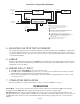
ILB-CP WITH TBTS TEST ACCESSORY
ILBCP_TBTS.EPS
AC (NORMAL)
DRIVER
IOTA ILB-CP
EMERGENCY DRIVER
LED
LOAD
WHITE
WHITE
WHT/BLK
WHT/BLK
COMMON
UNSWITCHED
24/7 POWER
BLK/ORG (120 TO 277V, 50/60HZ)
AC INPUT (120 TO 277V)
SWITCHED OR
UNSWITCHED
HOT
TBTS
TEST ACCESSORY
RED (+)
BLUE (-)
RED/WHT (+)
BLUE/WHT (-)
LED INPUT(+)
LED INPUT (-)
LED OUTPUT (+)
LED OUTPUT (-)
UNIT
CONNECTOR
WHT/RED
RED OR RED/BLK (+)
ATTENTION: DO NOT MATE UNIT CONNECTOR UNTIL
INSTALLATION IS COMPLETE AND AC POWER IS SUPPLIED.
TEST ACCESSORY LEADS-OBSERVE PROPER
POLARITY WIRING.
NO POLARITY ON WHT/BLK LEADS. USE EITHER LEAD FOR
CONNECTION TO BUILDING COMMON (SWITCHED OR UNSWITCHED)
AND OTHER FOR CONNECTION TO AC DRIVER.
CONNECT UNSWITCHED POWER. IF A SINGLE BUILDING
COMMON IS PRESENT, CONNECT THE WHITE WIRE TO THE COMMON.
IF A SEPARATE UNSWITCHED CONDUCTOR FEED IS PRESENT,
CONNECT THE WHITE LEAD TO THE COMMON FROM THE
UNSWITCHED FEED.
MATE UNIT CONNECTOR AFTER INSTALLATION IS
COMPLETE AND AC POWER IS SUPPLIED
WHT
RED
Illustration 2: Typical Wiring Diagram