
Installation Guide

Page 2
INSTALLATION INSTRUCTIONS
CAUTION: Before installing, make certain the A.C. power is off and the ILB unit
connector is disconnected.
1. FIXTURE
The ILB-CP can be used with most LED loads that operate at 10-60 VDC. See the ILB Model Specification
Chart for output specifications of the unit being installed.
1. The ILB-CP series has been evaluated to and found compliant to UL standard 924. The as-installed
performance of system must meet or exceed all Federal, State, and Local code requirements.
2. Refer to Addendum 11042014 for detailed specifications and methods to calculate emergency light levels.
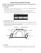
2. MOUNTING THE ILB
The ILB should be mounted on or nearby the fixture above the ceiling. The flex conduit marked “A” should be
wired into the driver/lamp compartment or to an electrical junction box on the fixture which allows access to the
fixture connections. Refer to Illustration 1 for typical mounting.
When battery packs are remote mounted, consult Customer Service for the maximum allowable distance between
the battery pack and the load.
Illustration 1 Downlight Fixture
FLEX “A”
JUNCTION
BOX
CEILING
TILE
A.C. BALLAST &
LAMP SOCKET COMPARTMENT
FLEX “B”
SWITCH BOX
TEST SWITCH
CHARGE LIGHT
ILB
TEST
ACCESSORIES
LED FIXTURE
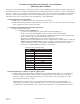
TBTS
ILB-CP05
ILB-CP07
ILB-CP10
5 WATTS
7 WATTS
10 WATTS
ILB MODEL SPECIFICATION CHART
OUTPUT POWER (CONSTANT)
ILB-CP12 12 WATTS
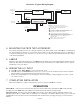
3. WIRING
Refer to Illustration 2 for the appropriate wiring of the LED load and driver. Install in accordance with the
National Electrical Code and local regulations. For additional wiring diagrams consult Customer Service.