
User manual


Copyright IXXAT Automation GmbH
CAN-CR2xx - Manual, V2.0
Indicators and connections
10
the device on the DIN rail. The ground of the CAN bus interface is connected to
earth via a 1 MΩ resistor and a 10 nF capacitor.
For best noise immunity results, the shields of the CAN cables have to be
grounded.
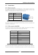
2.3.3 DIN rail bus and TBUS plug
The CAN-CR200 and CAN-CR210/FO have a DIN rail bus. With this interface the
device can be connected to other CAN-CR200 or CAN-CR210/FO devices. Using
this feature you have the possibility to realize a star topology with up to 240 CAN
connections.
For the DIN rail bus so called TBUS plugs are necessary. This plugs were pressed
into the DIN rail. More detailed information can be read in chapter 4.2
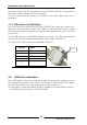
The signals of the DIN rail bus are described in Table 2-5
Pin No. Signal
1 CAN-High
2 CAN-Low
3 GND
4 -
5 -
Table 2-5 Pin allocation of the DIN rail bus
2.4 CAN bus termination
The CAN-Repeater offers the possibility to add bus termination resistors to each
CAN network connected to the device. This feature is realized with a DIP switch
for each CAN channel. For more details please refer to chapter 3.1.
As an accessory a bus termination resistor is available as a feed through connect-
or at IXXAT (ordering number 1.04.0075.03000).
Pin 1