
User manual


Copyright IXXAT Automation GmbH
CAN-CR2xx - Manual, V2.0
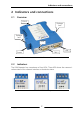
Indicators and connections
8
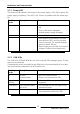
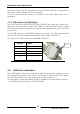
2.2.1 Power-LED
The Power LED P indicates the status of the power supply. If the LED is green, the
power supply is working. If the LED is off, there is a problem with the power sup-
ply.
Flashing
mode
Description Causes/Hints
Off No power
• Device not connected to a power sup-
ply
• Fuse of the device damaged
• Internal power supply damaged
green Power ok
• Device fully functional
red Device is resetted
• After power-up the device is set into
reset and the LED is red for the dura-
tion of the reset. The normal duration
period is about 200 ms.
• Power supply out of order, the internal
voltage is below the necessary level.
Table 2-1 States of the Power-LED
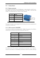
2.2.2 CAN LEDs
The CAN LEDs 1,2 and 3 flashes on each received CAN message green, if there
was no error detected.
If transmission errors (received bits are different to the transmitted bits) or a dom-
inant-lock state are detected, the LEDs flashes red.
Flashing
mode
Description Causes/Hints
off No CAN
communication
• No CAN communication
• Device not connected to CAN
green / green
blinking
CAN communication
• With each CAN message the LED is
triggered
red blinking CAN communication,
but errors
• The received bits are not equal to the
transmitted ones.
red Dominant-lock
• An external device applies a perma-
nent dominant level to the CAN
Table 2-2 States of the CAN LEDs