
User manual


Copyright IXXAT Automation GmbH
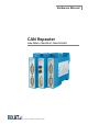
CAN-CR2xx - Manual, V2.0
Indicators and connections
9
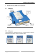
2.3 Connections
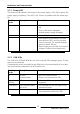
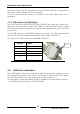
2.3.1 Power connector
For the power connection of the CAN-Repeater, a screw terminal is used. For wir-
ing, please ensure that the cross-sectional area of the cable is not less than
0.2mm². The maximum area is 2.5mm² for the connector.
Pin No. Signal
1 +9 V bis +32 V DC
2 0 V
3 -
4 -
Table 2-3 Pin allocation of the power connector
The power connector is just plugged into the housing and can be removed with a
screwdriver or similar tool.
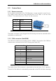
2.3.2 CAN connector (Sub-D9M)
The CAN bus interfaces are according to ISO 11898-2. The signals of the CAN bus
interfaces are connected to the Sub D-9 plugs (see Table 2-4).
Pin No. Sub D9 Signal
1 -
2 CAN-Low
3 CAN-GND
4 -
5 -
6 -
7 CAN-High
8 -
9 -
Table 2-4 Pin allocation of the CAN bus connector
The shield of the CAN connector is connected to the earth via a 10 nF capacitor.
The earth of the device is automatically connected to the DIN rail after mounting
Pin 1