PC CAN Interface CAN-IB Series for PCI/PCIexpress USER MANUAL 4.01.0230.20000 3.
Important User Information Liability Every care has been taken in the preparation of this document. Please inform HMS Industrial Networks of any inaccuracies or omissions. The data and illustrations found in this document are not binding. We, HMS Industrial Networks, reserve the right to modify our products in line with our policy of continuous product development. The information in this document is subject to change without notice and should not be considered as a commitment by HMS Industrial Networks.
Table of Contents 1 2 Page User Guide ........................................................................................................................... 3 1.1 Target Group...................................................................................................................3 1.2 Related Documents ..........................................................................................................3 1.3 Document History ........................................................
9 Support/Return Hardware................................................................................................ 21 9.1 Support ........................................................................................................................ 21 9.2 Return Hardware ........................................................................................................... 21 10 Disposal........................................................................................................
User Guide 1 3 (26) User Guide Please read the manual carefully. Make sure you fully understand the manual before using the product. 1.1 Target Group This manual addresses trained personnel who are familiar with CAN, CAN FD and the applicable standards. Only ESD trained staff is authorized to install the interface. The contents of the manual must be made available to any person authorized to use or operate the product. 1.2 1.3 1.
User Guide 1.5 4 (26) Conventions Instructions and results are structured as follows: ► instruction 1 ► instruction 2 → result 1 → result 2 Lists are structured as follows: • item 1 • item 2 Bold typeface indicates interactive parts such as connectors and switches on the hardware, or menus and buttons in a graphical user interface. This font is used to indicate program code and other kinds of data input/output such as configuration scripts.
Safety Instructions 5 (26) 2 Safety Instructions 2.1 Information on EMC Risk of interference to radio and television if used in office or home environment! Use exclusively included accessories. Make sure that the shield of the interface is connected with the device plug and the plug on the other side. Use exclusively shielded cables. 2.2 2.3 General Safety Instructions ► Protect product from moisture and humidity. ► Protect product from too high or too low temperature (see Technical Data, p. 20).
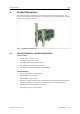
Product Description 4 6 (26) Product Description PCIe interfaces (apart from PCIe Mini) are available as standard and low-profile version. PCI interfaces are available as standard version. The low-profile version is expandable with a D-Sub 9 connector on a second slot bracket. Fig. 1 4.
Product Description 7 (26) CAN-IB300/400/PCI 4.2 • PCI CAN Interface • 5 V and 3.3 V compatible • CAN-IB300/PCI, passive interface • CAN-IB400/PCI, active interface • PCI interface compliant with PCI local bus specification Rev. 2.2 • galvanically isolated CAN-IB500/600/PCIe Common Features • supports CAN-FD (ISO and non-ISO) and CAN 2.
Product Description 4.3 8 (26) CAN-IB120/PCIe Mini and CAN-IB520/PCIe Mini Common features • Single lane (x1) PCI express card • PC interface compliant with PCI express base specification, revision 1.1 • form factor F2: Full-mini with bottom-side keep outs • dimensions according to PCI express Mini Card electromechanical specification, revision 1.
Installation 9 (26) 5 Installation 5.1 Installing the Software For the operation of the interface a driver is needed. Windows ► Install the VCI driver (see Installation Guide VCI Driver). Linux and Real-Time Operating Systems ► 5.2 Observe information about supported operating systems and interfaces on www.ixxat.com. Installing the Hardware Risk of ESD damages caused by improper handling! Use ESD protective measures to avoid equipment damage. ► Make sure that the VCI driver is installed.
Connections 10 (26) 6 Connections 6.1 Overview 3 6 2 1 4 Fig. 2 6.2 5 Connections 1 CAN 1 2 CAN 2 (exclusively in standard version) 3 Fieldbus expansion connector channel 2 (option) 4 Fieldbus expansion connector channel 1 (option) 5 PCI/PCIe connector 6 Expansion board connector (option) CAN Bus The bus coupling can optionally be galvanically isolated. With galvanic isolation the shield of the CAN connector is connected to CAN ground through a 1 MΩ resistor and a 10 nF capacitor.
Connections 11 (26) Low-Profile Version 1 Fig. 3 Low-profile version In the low-profile version, only the D-Sub 9 connector of CAN 1 is implemented. It is possible to output the signals of CAN 2 to a second slot bracket. ► 6.3 To connect the second slot bracket to the interface, plug the ribbon cable in connector (1) on the interface and in the connector on the second slot bracket.
Connections 6.4 12 (26) PCIe Mini 1 2 3 Fig. 4 Connections PCIe Mini 1 CAN 1, Pin 1 2 CAN 2, Pin 1 3 PCIe Mini card connector Pin Allocation CAN Connector Pin no. Signal Color 1 CAN-High Red 2 CAN-Low Yellow 3 CAN GND Black The CAN connector type is SM03B-SURS-TF by JST. The counterpart is 03SUR-32S by JST. A preassembled open-style cable for each CAN connector is included. PC CAN Interface User Manual 4.01.0230.20000 3.
Expansions 13 (26) 7 Expansions 7.1 Fieldbus Expansion Fig. 5 Fieldbus expansion If there is a low-speed CAN transceiver on the fieldbus expansion, it is possible to switch via software between the high-speed CAN transceiver on the interface and the low-speed CAN transceiver on the fieldbus expansion. The signals of the fieldbus modules are connected to the appropriate D-Sub 9 connector. Simultaneous operation of low-speed CAN and LIN is also possible.
Expansions 7.1.2 14 (26) Installation 1 3 Fig. 6 2 4 CAN interface with fieldbus expansions 1 Fieldbus expansion channel 2 2 Fieldbus expansion connector channel 2 3 Fieldbus expansion channel 1 4 Fieldbus expansion connector channel 1 ► Plug the expansion in the corresponding expansion connector. ► Make sure that the expansion is properly inserted in the socket. → Interface detects the installed expansions automatically.
Expansions 7.2 15 (26) CAN Expansion Board 3 4 2 7 1 5 Fig.
Expansions 7.2.3 16 (26) Fieldbus Expansions The fieldbus expansion connectors can be used to extend each CAN circuit with fieldbus expansions for additional fieldbuses. The signals of the additional fieldbuses are applied to the corresponding CAN connector. 7.3 ► Observe information about available fieldbus expansions and the compatibility with CAN interfaces on www.ixxat.com. ► Install the expansion (see Installation, p. 14). MultiCAN Expansion Fig.
Expansions 17 (26) Installation 3 4 2 1 Fig. 9 CAN interface with MultiCAN-PB expansion 1 CAN 1/3 2 CAN 2/4 3 MultiCAN-PB 4 Fieldbus expansion connectors ► Install the expansion (see Installation, p. 14). ► Observe different pin allocation of D-Sub 9 connector. Pin Allocation Using MultiCAN-PB Pin No.
Expansions 7.3.2 18 (26) MultiCAN-PB/LP 3 4 1 3 2 Fig. 10 4 2 CAN interface and CAN expansion board with MultiCAN-PB/LP expansion 1 CAN 1/2 2 CAN 3/4 3 MultiCAN-PB/LP 4 Fieldbus expansion connectors If used in conjunction with low profile CAN interfaces the expansion redirects channel CAN 2 to the CAN 1 connector. If used in conjunction with the CAN expansion board the expansion redirects channel CAN 4 to the CAN 3 connector. The galvanic isolation of CAN channels remains.
Expansions 19 (26) Installation ► Install the expansion (see Installation, p. 14). ► Observe different pin allocation of D-Sub 9 connector. Pin Allocation Using MultiCAN-PB/LP Pin No. Signal CAN 1/2 Signal CAN 3/4 1 CAN2-Low (high-speed) CAN4-Low (high-speed) 2 CAN1-Low (high-speed) CAN3-Low (high-speed) 3 GND1 GND3 4 CAN2-High (high-speed) CAN4-High (high-speed) 5 6 GND2 — GND4 — 7 CAN1-High (high-speed) CAN3-High (high-speed) 8 — — 9 — — PC CAN Interface User Manual 4.01.
Technical Data 20 (26) 8 Technical Data 8.1 PCI/PCIe CAN transceiver (low-speed): TJA1054, via optional fieldbus expansion LIN transceiver TJA1020T, via optional fieldbus expansion Operating temperature range 0 °C to +70 °C Storage temperature range -40 °C to +85 °C Galvanic isolation 1 kV for 1 second Relative humidity 10 % to 95 %, no condensation CAN propagation delay With galvanic isolation typical 6 ns, max.
21 (26) Support/Return Hardware 9 Support/Return Hardware Observe the following information in the support area on www.ixxat.com: 9.1 9.2 10 • information about products • FAQ lists • installation notes • updated product versions • updates Support ► For problems or support with the product request support at www.ixxat.com/support. ► If required use support phone contacts on www.ixxat.com. Return Hardware ► Fill in the form for warranty claims and repair on www.ixxat.com.
This page intentionally left blank
Appendix A: Regulatory Compliance 23 (26) A Regulatory Compliance A.1 EMC Compliance (CE) The product is in compliance with the Electromagnetic Compatibility Directive. More information and the Declaration of Conformity is found at www.ixxat.com. A.2 FCC Compliance Statement This device complies with Part 15 of the FCC Rules. Operation is subject to the following two conditions: ► This device may not cause harmful interference.
Appendix A: Regulatory Compliance A.3 24 (26) Disposal and recycling You must dispose of this product properly according to local laws and regulations. Because this product contains electronic components, it must be disposed of separately from household waste. When this product reaches its end of life, contact local authorities to learn about disposal and recycling options, or simply drop it off at your local HMS office or return it to HMS. For more information, see www.hms-networks.com.
This page intentionally left blank
last page © 2019 HMS Industrial Networks Box 4126 300 04 Halmstad, Sweden info@hms.se 4.01.0230.20000 3.