
Datasheet

LCB110
www.clare.com
5
R07
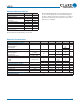
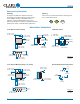
MECHANICAL DIMENSIONS
Manufacturing Information
RoHS
2002/95/EC
e
3
Pb
Soldering
For proper assembly, the component must be
processed in accordance with the current revision
of IPC/JEDEC standard J-STD-020. Failure to
follow the recommended guidelines may cause
permanent damage to the device resulting in impaired
performance and/or a reduced lifetime expectancy.
Washing
Clare does not recommend ultrasonic cleaning or the
use of chlorinated solvents.
6.350 ± 0.127
(0.250 ± 0.005)
2.540 ± 0.127
(0.100 ± 0.005)
7.620 ± 0.127
(0.300 ± 0.005)
5.080 ± 0.127
(0.200 0.005)
6 - 0.800 DIA.
(6 - 0.031 DIA.)
6-Pin DIP Thru-Hole Package
PC Board Pattern
0.254 TYP
(0.010 TYP)
9.144 ± 0.508
(0.360 ± 0.020)
7.239 TYP
(0.285 TYP)
7.620 ± 0.254
(0.300 ± 0.010)
3.302 ± 0.051
(0.130 ± 0.002)
4.064 TYP
(0.160 TYP)
0.457 ± 0.076
(0.018 ± 0.003)
Dimensions
mm
(inches)
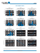
8.382 ± 0.381
(0.330 ± 0.015)
2.54 ± 0.127
(0.100 ± 0.005)
6.350 ± 0.127
(0.250 ± 0.005)
1.651 ± 0.254
(0.065 ± 0.010)
0.254 ± 0.0127
(0.010 ± 0.0005)
7.620 ± 0.254
(0.300 ± 0.010)
0.635 ± 0.127
(0.025 ± 0.005)
6-Pin Surface Mount Package (”S” Suffix)
Recommended PCB Land Pattern
Dimensions
mm
(inches)
3.302 ± 0.051
(0.130 ± 0.002)
4.445 ± 0.254
(0.175 ± 0.010)
2.54
(0.10)
8.90
(0.3503)
1.65
(0.0649)
0.65
(0.0255)
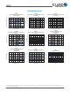
8.382 ± 0.381
(0.330 ± 0.015)
2.54 ± 0.127
(0.100 ± 0.005)
9.524 ± 0.508
(0.375 ± 0.020)
6.350 ± 0.127
(0.250 ± 0.005)
0.457 ± 0.076
(0.018 ± 0.003)
1.651 ± 0.254
(0.065 ± 0.010)