0 SERIES, ELECTRICALLY HEATED, ROUND DISHMACHINES INSTALLATION & OPERATION MANUAL FOR JACKSON MODELS: 10A 10AB 10APRB 10U HIGHER HOOD OPTION An February 24, 2004 P/N 7610-100-01-00 (Revision E) Company Jackson MSC, INC. P.O. BOX 1060 HWY. 25E BARBOURVILLE, KY. 40906 FAX (606) 523-9196 PHONE (606) 523-9795 www.jacksonmsc.
MANUFACTURERS WARRANTY ONE YEAR LIMITED PARTS & LABOR WARRANTY ALL NEW JACKSON DISHWASHERS ARE WARRANTED TO THE ORIGINAL PURCHASER TO BE FREE FROM DEFECTS IN MATERIAL OR WORKMANSHIP, UNDER NORMAL USE AND OPERATION FOR A PERIOD OF (1) ONE YEAR FROM THE DATE OF PURCHASE, BUT IN NO EVENT TO EXCEED (18) EIGHTEEN MONTHS FROM THE DATE OF SHIPMENT FROM THE FACTORY.
REVISION REVISION DATE MADE BY APPLICABLE ECN DETAILS D 02-24-04 MAW N/A ADDED 10U PHOTO INSTALLATION GUIDE AND ALL 10U INFORMATION i
NOMENCLATURE FOR THE MODELS COVERED IN THIS MANUAL: 10 SERIES 10A = 10 without a booster tank 10AB = 10 with a booster tank 10APRB = 10 with a booster tank and a power rinse pump 10U = 10 with a booster tank, a 4” shorter hood, and 9” shorter legs Higher Hood Option = A hood that is 5” higher than the standard hood Jackson MSC Inc. provides technical support for all of the dishmachines detailed in this manual.
TABLE OF CONTENTS SECTION I. II. III. IV. V.
SECTION 1: SPECIFICATION INFORMATION 1
SECTION 1: SPECIFICATION INFORMATION 10 SERIES SPECIFICATIONS PERFORMANCE/CAPABILITIES ELECTRICAL REQUIREMENTS OPERATING CAPACITY (RACKS/HOUR) WASH PUMP MOTOR HP 1/2 RINSE PUMP MOTOR HP (10APRB ONLY) 1/2 MODEL AMPS RACKS PER HOUR 45 DISHES PER HOUR 950 GLASSES PER HOUR 950 OPERATING CYCLE (SECONDS) VOLTS HERTZ PHASE 10A 208 60 1 8.23 10A 220 60 1 8.23 WASH TIME 60 10AB/10U 208 60 1 38.8 RINSE TIME 10 10AB/10U 208 60 3 25.
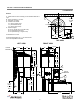
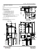
SECTION 1: SPECIFICATION INFORMATION 10A DIMENSIONS NOTES: A - Water inlet 1/2” NPT. Plumbing can be directed either left or right. B - Drain connection 1 1/2” NPT C - Electrical connection D - Clearance for dishes: 10” (10A 4” shorter hood) 14” (10A standard hood) 19” (10A 5” higher hood) E - Machine height: 45 1/2” (9” shorter leg, 4” shorter hood) 58 1/4” (standard leg & hood) 63 1/4” (standard leg, 5” higher hood) B 14 7/8” TO THE WALL 1 13/16” 9” 5 1/4” All dimensions in inches.
SECTION 1: SPECIFICATION INFORMATION 10AB/10APRB/10U DIMENSIONS NOTES: F A - Water inlet 1/2” NPT. Plumbing can be directed either left or right.
SECTION 1: SPECIFICATION INFORMATION 10 SERIES TABLE DIMENSIONS Legend A - 10” High backsplash, 2” turnback at 45B B - 3” High, 1 1/2” diameter rolled edge C - Scrap block D - Scrap basket with slide bars E - 20” x 20” x 5” deep pre-rinse sink F - Heavy duty pre-rinse G - 20” Slanted wall mounted overshelf 42” long H - 3 1/2” hole for sink drain with basket drain I - 1 7/8” hole for hood support piping 10 1X PACKAGE 10 2X PACKAGE 10 3X PACKAGE 5
SECTION 2: INSTALLATION/OPERATION INSTRUCTIONS 6
SECTION 2: INSTALLATION/OPERATION INSTRUCTIONS INSTALLATION INSTRUCTIONS Jackson MSC Inc. provides technical support for all of the dishmachines detailed in this manual. We strongly recommend that you refer to this manual before making a call to our technical support staff. Please have this manual with you when you call so that our staff can refer you, if necessary, to the proper page. Technical support is available from 8:00 a.m. to 5:00 p.m. (EST), Monday through Friday.
SECTION 2: INSTALLATION/OPERATION INSTRUCTIONS INSTALLATION INSTRUCTIONS LEVEL THE DISHMACHINE: The dishmachine is designed to operate while being level. This is important to prevent any damage to the machine during operation and to ensure the best results when washing ware. The unit comes with adjustable bullet feet, which can be turned using a pair of channel locks or by hand if the unit can be raised safely.
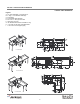
SECTION 2: INSTALLATION/OPERATION INSTRUCTIONS INSTALLATION INSTRUCTIONS ALIGNING THE MACHINE: Adjust the machine base to line up hole in table with hole in support block (Fig. 11). (Fig. 11) INSTALLING THE INTERNAL VACUUM BREAKER: Insert internal vacuum breaker pipe into hood support block pin end down (Fig.12). WARNING: Internal vacuum breaker pipe must be installed or there will be a hazard to the operator. (Fig. 12) INSTALLING THE HOOD ASSEMBLY: Make sure there are two “Orings” (Fig.
SECTION 2: INSTALLATION/OPERATION INSTRUCTIONS INSTALLATION INSTRUCTIONS PLUMBING THE DISHMACHINE: All plumbing connections must comply with all applicable local, state, and national plumbing codes. The plumber is responsible for ensuring that the incoming water line is thoroughly flushed prior to connecting it to any component of the dishmachine. It is necessary to remove all foreign debris from the water line that may potentially get trapped in the valves or cause an obstruction.
SECTION 2: INSTALLATION/OPERATION INSTRUCTIONS INSTALLATION INSTRUCTIONS FINAL CHECK: Check all fittings and connections before and after first 10 cycles. Deliver Installation/Operation Manual to site manager. Contact Jackson for free performance and installation check.
SECTION 2: INSTALLATION/OPERATION INSTRUCTIONS OPERATION INSTRUCTIONS PREPARATION: 1. Ensure that the pump intake strainer (1) and basket overflow strainer (2) are inserted and tight. 2. Ensure that the wash and rinse arms are installed and secure. 3. Remove all solid wastes in order to avoid obstructing filters, drain and wash and rinse arms. 4. Ware that is encrusted with soil should be presoaked prior to being placed in the machine. 5.
SECTION 2: INSTALLATION/OPERATION INSTRUCTIONS DETERGENT CONTROL Detergent usage and water hardness are two factors that contribute greatly to how efficiently your dishmachine will operate. Using detergent in the proper amount can become, in time, a source of substantial savings. A qualified water treatment specialist can tell you what is needed for maximum efficiency from your detergent, but you should still know some basics so you’ll understand what they are talking about.
SECTION 3: PREVENTATIVE MAINTENANCE 14
SECTION 3: PREVENTATIVE MAINTENANCE PREVENTATIVE MAINTENANCE Proper maintenance of your Jackson dishmachine will insure optimum service with a minimum of down time. 1. To a. b. c. d. e. f. g. h. i. delime the booster tank. Remove the support pipe nut and lift the whole hood assembly away from the unit. Loosen the fitting going into bottom side of booster tank. Drain approximately 2 to 3 cups out of the tank.
SECTION 4: ELECTRICAL SCHEMATICS 16
SECTION 4: ELECTRICAL SCHEMATICS 10A, 10AB/10U, 10APRB 10A 208/220V 1 PHASE 09905-002-57-63 A L1 TERMINAL BOARD #1 WASH MOTOR CIRCUIT BREAKER CUSTOMER SERVICE WASH HEATER L2 15 AMP RATING ½ HP 5.3 AMPS 630 WATTS 10AB/10U 208/220V 1 PHASE 09905-105-33-59 B L1 RINSE HEATERS TERMINAL BOARD #1 WASH MOTOR CIRCUIT BREAKER CUSTOMER SERVICE WASH HEATER L2 6900 WATTS 15 AMP RATING ½ HP 5.3 AMPS 630 WATTS 10AB/10U 208/220V 3 PHASE L1 L3 WASH MOTOR WASH HEATER ½ HP 5.
SECTION 4: ELECTRICAL SCHEMATICS 10A WIRING DIAGRAM (208-230 VOLT, 60HZ, SINGLE PHASE) 18
SECTION 4: ELECTRICAL SCHEMATICS 10AB WIRING DIAGRAM (208-230 VOLT, 60HZ, SINGLE PHASE) 9905-000-54-97 19
SECTION 4: ELECTRICAL SCHEMATICS 10AB WIRING DIAGRAM (208-230 VOLT, 60HZ, THREE PHASE) 9905-002-55-90a 20
SECTION 4: ELECTRICAL SCHEMATICS 10APRB WIRING DIAGRAM (208-230 VOLT, 60HZ, SINGLE PHASE) 9905-002-55-91a 21
SECTION 4: ELECTRICAL SCHEMATICS 10APRB WIRING DIAGRAM (208-230 VOLT, 60HZ, THREE PHASE) 9905-002-55-92a 22
SECTION 5: JACKSON MAINTENANCE & REPAIR CENTERS 23
SECTION 5: JACKSON MAINTENANCE & REPAIR CENTERS ALABAMA TO HAWAII ALABAMA: CALIFORNIA: COLORADO (cont.): FLORIDA (cont.): JONES-McLEOD APPLIANCE SVC 1616 7TH AVE. NORTH BIRMINGHAM, AL 35203 (205) 251-0159 800-821-1150 FAX: (205) 322-1440 service@jones-mcleod.com BARKERS FOOD MACHINERY SERVICES 5367 SECOND STREET IRWINDALE, CA 91706 (626) 960-9390 800-258-6999 FAX: (626) 337-4541 service@barkers.
SECTION 5: JACKSON MAINTENANCE & REPAIR CENTERS IDAHO TO MISSISSIPPI IDAHO: IOWA (cont.): LOUISIANA (cont.): MASSACHUSETTS: RON'S SERVICE 703 E 44TH STREET STE 10 GARDEN CITY, ID 83714 (208) 375-4073 FAX: (208) 375-4402 CONES REPAIR SVC. 1056 27TH AVENUE SW CEDAR RAPIDS, IA 52404 (319) 365-3325 800-747-3326 FAX: (319) 365-0885 BANA PARTS INC. 4028 GREENWOOD ROAD SHREVEPORT, LA 71109 (318) 631-6550 800-832-6550 FAX: (318) 636-5675 ACE SERVICE CO. 95 HAMPTON AVE.
SECTION 5: JACKSON MAINTENANCE & REPAIR CENTERS MISSISSIPPI TO NORTH CAROLINA MISSISSIPPI (cont.): NEVADA: NEW JERSEY (cont.): NEW YORK (cont.): GCS SERVICE INC. 5755 GALLANT DRIVE. JACKSON, MS 39206 (601) 956-7800 800-274-5954 FAX: (601) 956-1200 HI TECH COMMERCIAL SVC 400 E. MEAD BLVD. LAS VEGAS, NV 89030 (702) 649-4616 (877) 924-4832 FAX: (702) 649-4607 ELMER SCHULTZ SERVICES 201 WASHINGTON AVE. PLEASANTVILLE, NJ 08232 (609) 641-0317 800-378-1641 FAX:(609) 641-8703 elmer2@erols.
SECTION 5: JACKSON MAINTENANCE & REPAIR CENTERS NORTH CAROLINA TO TEXAS NORTH CAROLINA (cont.): OHIO (cont.): PENNSYLVANIA (cont.): SOUTH CAROLINA (cont.): AUTHORIZED APPLIANCE SERVICE CENTER 109 HINTON AVE. WILMINGTON, NC 28403 (910) 313-1250 FAX: (910) 313-6130 GCS SERVICE INC. 2830 JOHNSTON RD.
SECTION 5: JACKSON MAINTENANCE & REPAIR CENTERS TEXAS TO WYOMING/CANADA TEXAS (cont.): VIRGINIA: WISCONSIN (cont.): COMMERCIAL KITCHEN REPAIR CO. 1377 N BRASOS P.O BOX 831128 SAN ANTONIO, TX 78207 (210) 735-2811 800-292-2120 FAX: (210) 735-7421 brock@commercialkitchen.com DAUBERS, INC. 7645 DYNATECH COURT SPINGFIELD, VA 22153 (703) 866-3600 800-554-7788 FAX: (703) 866-4071 daubers@aol.