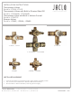
INSTALLATION INSTRUCTIONS Thermostatic Valves Part #’s: J-TH34, J-TH12 Thermostatic Valves with Built in Diverter/Shut Off Part #’s: J-TH34-686, J-TH34-688 Thermostatic Valve with Built in Volume Control Part #’s: J-THVC12 Diverter Valves Part #’s: J-20682, J-20686, J-20688 J-TH34 / J-TH12 Confidence from start to finish.® J-THVC12 J-TH34-686 / J-TH34-688 J-20682 J-20686 / J-20688 INSTALLER WARNING • • • Follow all applicable Local Plumbing Codes, Public Health and Safety Codes.
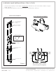
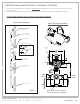
(1) ROUGH VALVE INSTALLATION (J-TH34 /J-TH12) 1. Position valve assembly so outer edge of finished wall is between min./max. thicknesses marked on rough in shield. See Fig. 1 2. Using appropriate fasteners, mount valve assembly to studs/blocking. See Fig. 1 INSTALLATION EXAMPLE VALVE ROUGH-IN SHIELD TO SHOWERHEAD OR OTHER PLUMBING ASSEMBLY 1" THICK FINISHED WALL OUTER EDGE SAMPLE HOLE IN WALL 3 5/8" 4½" Ø Max 2 5/16" Hot Inlet CREATED 5.2014 JACLO.
(1) ROUGH VALVE INSTALLATION (J-THVC12) 1. Position valve assembly so outer edge of finished wall is between min./max. thicknesses marked on rough in shield. See Fig. 1 2. Using appropriate fasteners, mount valve assembly to studs/blocking. See Fig. 1 INSTALLATION EXAMPLE VALVE ROUGH-IN SHIELD WARM TO SHOWERHEAD OR OTHER PLUMBING ASSEMBLY 1" THICK FINISHED WALL OUTER EDGE ROTATE LEVER ROTATE LEV FOR VOLUM CONTROL SAMPLE HOLE IN WALL 4½" Ø Max 5 3/4" 3 3/8" 4 3/16" 5 1/2" REF.
(1) ROUGH VALVE INSTALLATION (J-20682 / J-20686 / J-20688) 1. Position valve assembly per Fig. 1 2. Using appropriate fasteners, mount valve assembly to studs/blocking. See Fig. 1 INSTALLATION EXAMPLE TO SHOWERHEAD OR OTHER PLUMBING ASSEMBLY J-20682 1" THICK FINISHED WALL OUTER EDGE 3 1/4" 4-1/4" MAX 3 1/4" DIVERTER SAMPLE HOLE IN WALL 1" Ø Max J-20686 / J-20688 3 9/16" B PORT 3 9/16" 1 11/16" OPTIONAL VOLUME CONTROL A PORT C PORT 1/2" NPS 3x INLET TO TUB SPOUT ONLY Figure 1 CREATED 5.
(1) ROUGH VALVE INSTALLATION (J-TH34-686/J-TH34-688) 1. Position valve assembly so outer edge of finished wall is between min./max. thicknesses marked on rough in shield. See Fig. 1 2. Using appropriate fasteners, mount valve assembly to studs/blocking using mounting holes. See Fig. 1 Diverter and Thermostatic valve are factory sealed, do not separate! INSTALLATION EXAMPLE VALVE ROUGH-IN SHIELD TO SHOWERHEAD OR OTHER PLUMBING ASSEMBLY 1" THICK FINISHED WALL OUTER EDGE THERM.
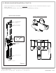
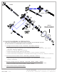
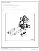
J-20682 13 14a 14b 15 1 J-20686 / J-20688 7 2 16 5 6 3 4 11 9 12 10 8 TRIM KIT SUPPLIED SEPARATELY (VARIES W/ MODEL #) 17 (2) VALVE DISASSEMBLY & PREPARATION THIS STEP IS REQUIRED TO FACILITATE VALVE FLUSHING AND ELIMINATE THE RISK OF HEAT DAMAGE TO COMPONENTS WHILE SOLDERING A. Cartridge removal (J-TH34, J-TH12, J-TH34-686, J-TH34-688, J-THVC12) i. Remove Phillips head screw and rough in shield. Do not discard screw or shield! ii. Note position of the limit stops (#6).
ITEM QUANTITY DESCRIPTION NOTES 1 1 Thermostatic Body 2 1 Thermostatic Cartridge 3 1 Thermostatic Cartridge Locknut 4 1 Thermostatic Limit Stop Ring 5 1 "C" Clip 6 2 Limit Stops 7 1 Cold Check Stop Assembly 8 1 Hot Check Stop Assembly 9 2 Check Stop Locknut 10 1 Sleeve Supplied w/ Trim Kit 11 1 Dial Pointer Supplied w/ Trim Kit 12 1 Spline Adapter Supplied w/ Trim Kit 13 1 Diverter Body 14a 1 2 Way Diverter Cartridge 14b 1 3 Way Diverter Cartridge 15 1 D
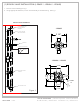
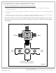
(3) PLUMB ROUGH USING APPROPRIATE FITTINGS Diverter and Thermostatic valve are factory sealed, do not separate! A. Plumb hot and cold inlets on thermostatic body. Part #’s: J-TH34. J-TH12, J-TH34-686, J-TH34-688, J-THVC12. See Fig. 3 B. If using lower port on thermostatic body, a separate volume control is required. If not, port must be plugged. See Fig. 3 C. Select diverter ports to be used. A, B, C and plumb with appropriate fittings.
(4) FLUSH SYSTEM A. Install flush adapters. See Fig. 4 B. Turn on water, flush system for 30 seconds minimum. C. Turn off water and remove flush adapters. Note: VALVE MUST BE FLUSHED TO AVOID DAMAGE TO INTERNAL PARTS! THERM./DIVERTER CHECK STOP ASSEMBLY FLUSH ADAPTERS CHECK STOP LOCKNUT Figure 4 j a c l o i n d u s t r i e s | 129 Dermody Street Cranford, NJ 07016 p 908.653.4433 | 800.852.3906 f 908.653.1717 | 800.852.4133 CREATED 5.2014 JACLO.
(5) Reassemble Thermostatic Valve & Diverter A. Reassemble in reverse order of steps in Fig. 2 i. Inspect and remove any debris in diverter body. ii. Insert diverter cartridge into body so protrusion on cartridge fits into holes in body located in the 6 o’clock position. See Fig. 2a iii. Install diverter lock nut using 1" wrench, tighten nut. iv. Inspect and remove any debris in the thermostatic valve body cartridge and check stop cavities. v.
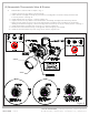
(6) System Check A. B. C. D. E. F. G. H. I. Close hot and cold check stops on thermostatic valve. See Fig. 5 Set diverter control to off position. See Fig. 6 Do not turn on water yet! Diverter of volume control must be off or damage to check stop seals may occur. Close volume control on bottom thermostatic port (if applicable). Turn on hot and cold main water supply. Check for leaks, repair if necessary. Open hot and cold check stops. See Fig.
PT. NE (6) System Check Continued J-THVC12 J-20682 B ON BC ON AB ON B PORT A ON C PORT A PORT C ON INLET (7) Reinstall rough in shield 3/8" DIA. 1/2" DIA. (8) Finished wall opening A. Minimum opening size opening to operate check stops, removing thermostatic and diverter cartridges is required. B. See Fig. 1 for maximum finished wall opening. (9) Thermostatic valve set up A. Remove rough in shield and discard if trim is to be installed after valve setup. B. Remove max temp.
(10) Dial Pointer, Trim and Handle Installation A. B. C. D. E. F. Push the dial pointer on to sleeve with pointer on top at 12 o’clock position. See Fig. 7. Turn on diverter valve to allow water to flow. Measure water temperature and adjust to 100°F. Install dial assembly on to spindle aligning the 100° to the dial pointer. See Fig. 7 Place adhesive backed foam strip to back side of trim plate. Slide trim plate over sleeve against finished wall.
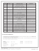
TROUBLE SHOOTING GUIDE PROBLEM Water leaks from shower head / tub spout when the volume control is shut off. Water is hot or cold but not mixing. Can not adjust water temperature properly. POSSIBLE CAUSE SOLUTION The shower head is trapping water behind the faceplate. Remove shower head and clean out the holes in the faceplate. Reinstall shower head. The volume control valve has been installed incorrectly. Arrow on side of volume control should be pointing away from the thermostatic valve.